
Single Phase Busbar (M6 Fork Type) — U-Type, 8–16 mm²
• Single phase busbar for MCBs/RCCBs; M6 clamping screws; 17.8 mm pitch.
• Standard lengths 210 / 1000 / 1016 mm; 12 / 54 / 57 modules; fork 12×12 mm.
• Finger-safe to DIN EN 50274; copper + FR PVC; 50–80 A (by cross-section).
Overview
This fork-type Single Phase Busbar is engineered for M6 clamping screws and modular protection devices (MCBs/RCCBs). It uses a constant 17.8 mm pitch with fork width/length 12 mm for fast alignment and secure, low-resistance joints. Standard lengths include 210 mm (12 modules), 1000 mm (54 modules) and 1016 mm (57 modules). The conductor is copper with flame-retardant PVC insulation and a finger-safe profile (DIN EN 50274) to support safe, reliable single-phase distribution.
Cross-sections 8 / 10 / 13 / 16 mm²Reference current 50–80 ARated voltage 415 V
Key Features
- U-shaped fork geometry provides secure contact and enlarged conductive area.
- M6 screw compatibility for robust clamping and low contact resistance.
- Single-phase busbar ideal for bridging adjacent modular devices.
- Standard pitch 17.8 mm matches common 18 mm modular widths.
- Fork width/length 12 mm for consistent terminal engagement.
- Lengths: 210 mm / 1000 mm / 1016 mm with 12 / 54 / 57 modules.
- Finger-safe design, DIN EN 50274; insulation with flame-retardant PVC.
- Customizable by the meter or pre-cut to required module counts.
Specifications
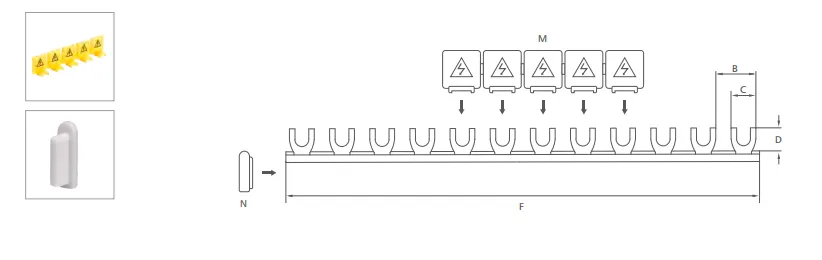
Standard data: Rated voltage 415 V • Pitch 17.8 mm • Fork width 12 mm • Fork length 12 mm • Finger-safe per DIN EN 50274 • Ambient −25 °C ~ +50 °C • Materials: copper conductor + FR PVC.
| Cross Section (mm²) | Distance / Pitch (mm) | Width of Fork (mm) | Length of Fork (mm) | Modules | Length (mm) | Reference Current |
|---|---|---|---|---|---|---|
| 8 | 17.8 | 12 | 12 | 12 | 210 | 50A |
| 10 | 17.8 | 12 | 12 | 12 | 210 | 63A |
| 13 | 17.8 | 12 | 12 | 12 | 210 | 70A |
| 16 | 17.8 | 12 | 12 | 12 | 210 | 80A |
| 8 | 17.8 | 12 | 12 | 54 | 1000 | 50A |
| 10 | 17.8 | 12 | 12 | 54 | 1000 | 63A |
| 13 | 17.8 | 12 | 12 | 54 | 1000 | 70A |
| 16 | 17.8 | 12 | 12 | 54 | 1000 | 80A |
| 8 | 17.8 | 12 | 12 | 57 | 1016 | 50A |
| 10 | 17.8 | 12 | 12 | 57 | 1016 | 63A |
| 13 | 17.8 | 12 | 12 | 57 | 1016 | 70A |
| 16 | 17.8 | 12 | 12 | 57 | 1016 | 80A |
Notes: Reference current is indicative by cross-section; verify with device manufacturer torque and ambient conditions. Custom pitch/lengths available upon request.
Dimension
Applications
- Single-phase power distribution in residential/commercial panels.
- Bridging adjacent MCBs/RCCBs on modular DIN rail devices.
- Industrial control cabinets and distribution boards.
- Switchboard OEM assembly and panel upgrades.
Why Choose Us
- High-conductivity copper with low contact resistance and reduced temperature rise.
- Safety & compliance: finger-safe design, DIN EN 50274; RoHS / CE / ISO 9001 ready.
- OEM customization: cross-section, cut-to-size, labeling, packaging options.
- Reliable supply: consistent quality control and export-ready documentation.
FAQ
What’s the difference between this 1-phase busbar and a four-pole busbar?
Which cross-section should I select?
What lengths and module counts are available?
Is the busbar finger-safe?
What torque should I apply to M6 terminals?
Get a Quote
Share your required length, module count, cross-section, quantity and delivery terms. Samples available for qualification.


