How to Choose Terminal Blocks for Control Panels
I’ve lost count of how many times a five-figure project delay came down to a five-cent component. It’s almost always the terminal block.
Let me tell you a story. A few years back, a client of mine was shipping 20 brand-new control panels for a semiconductor fab in Wuxi, China. The panels were at the port in Shanghai, ready to go. Then the call came. “Customs has flagged your shipment. The terminal blocks don’t have CCC marks.”
They had UL recognition. They had CE marks. They had everything you’d think you need for a high-spec industrial panel. But they didn’t have the one certification that mattered in China. The result? A scramble to source compliant replacements, air freight them to Shanghai, and clear the original rejection. The final bill for the oversight—including demurrage fees, expedited shipping, and late-delivery penalties—was a staggering $127,000. All because of terminal blocks.
This isn’t a far-fetched, worst-case scenario. For engineers and panel builders shipping globally, it’s a Tuesday. We obsess over the PLC, the VFDs, and the HMIs, but often treat the terminal block as an afterthought—a simple commodity. That’s a critical mistake. Choosing the right terminal block is not just about connecting wire A to wire B. It’s about ensuring the safety, reliability, and legal compliance of your entire system.
In this guide, I’m going to walk you through the bulletproof framework I’ve developed over 15+ years in the field. We’ll go beyond the spec sheet to help you choose the right terminal block, every single time, and avoid that gut-wrenching call from a client or a customs agent.
Part 1: The Anatomy of a Failure
Before you can choose the right terminal block, you need to understand how—and why—they fail. Most failures aren’t due to manufacturing defects; they’re caused by a mismatch between the component and the application. Let’s look at the three horsemen of terminal block apocalypse.
Thermal Stress: The Silent Killer
Heat is the number one enemy of electrical connections. If a terminal block gets too hot, its plastic housing can melt or warp, causing connections to loosen. This creates a vicious cycle: a loose connection increases electrical resistance, which generates even more heat, leading to catastrophic failure, short circuits, and even fire.
The main causes of thermal stress are:
- Overload Operation: Running more current through a block than it’s rated for. This is the most common and easily avoidable cause.
- Poor Contact: Loose wires, improperly torqued screws, or oxidation on the contacts increases resistance and generates heat at the connection point.
- Improper Installation: Cramming blocks together without adequate airflow prevents heat from dissipating.
Key Takeaway: The single most important rule to prevent thermal failure is the 150% Current Rule. Always select a terminal block with a current rating of at least 150% of your system’s maximum expected current. If your circuit is expected to draw 10A, use a block rated for at least 15A.
Mechanical Failure: The Shakes and Breaks
Control panels, especially those mounted on or near heavy machinery, are subject to constant vibration. This mechanical stress can wreak havoc on terminal connections.
- Vibration Effects: Over time, vibrations can cause screws to back out, leading to loose connections. In spring-based connections, severe vibration can cause wire fatigue or pull-out if not properly secured.
- Connection Type Mismatch: Using a connection technology that isn’t suited for the environment is a recipe for disaster. For instance, a standard screw terminal might be fine in a static environment, but in a high-vibration application like a stamping press or a rail car, a spring-clamp connection is far more reliable.
Environmental Degradation: The Slow Rot
The environment inside and outside the panel plays a huge role in a terminal block’s lifespan.
- Corrosion: In humid or chemically aggressive environments (like wastewater treatment plants or marine applications), the metal components of a terminal block can corrode. This rust and oxidation increases resistance, leading to thermal stress and eventual failure.
- Insulation Breakdown: Dust, moisture, and chemical vapors can degrade the block’s insulating housing. This can lower its dielectric strength, creating a risk of short circuits between adjacent terminals. This is where an appropriate IP (Ingress Protection) rating becomes critical.
Part 2: The 4-Step Selection Framework
Now that we know what we’re up against, let’s build our selection process. Think of it as a four-part checklist to ensure you’ve covered all your bases when you choose a terminal block.
Step 1: Define Your Electrical Universe
This is the foundation. Get these numbers wrong, and nothing else matters.
- Current Rating: We’ve already discussed the 150% rule. This is non-negotiable.
- Voltage Rating: The block’s voltage rating must be greater than your maximum system voltage, including any potential surges. A block’s voltage rating is determined by its pitch (the distance from the center of one pole to the next) and the quality of its insulation material.
- Wire Size/Gauge: The terminal block must be rated to accept the wire gauge (AWG in North America) you’re using. Most blocks accept a range (e.g., 26-12 AWG). Attempting to force a wire that’s too large or too small into a terminal will result in an unreliable connection.
- Pole Count: This is simply the number of individual circuits you need to connect. Terminal blocks are available from single-pole up to dozens of poles.
| Specification | Pro-Tip | Why It Matters |
|---|---|---|
| Current Rating | Select a block rated for 150% of max system current. | Prevents overheating, melting, and fire hazards. This is the most critical safety factor. |
| Voltage Rating | Choose a rating higher than your system’s max voltage to account for surges. | Prevents dielectric breakdown and short circuits between poles. |
| Wire Gauge (AWG) | Check the block’s accepted wire range. Don’t guess. | Ensures a secure physical and electrical connection. The wrong size leads to loose wires or damage. |
| Pole Count | Consider using interlocking modules for flexibility. | Interlocking blocks (usually 2 or 3 poles) let you build custom pole counts and color-code circuits. |
Step 2: Conquer Your Mechanical & Environmental Reality
This step is about matching the block to its physical environment and the demands of installation and maintenance.
Connection Method
This is one of the most important decisions you’ll make. There are three primary technologies:
- Screw Clamp: The classic method. A screw tightens a clamp onto the wire. It’s versatile and accepts a wide range of wire types, including those without ferrules. However, it’s the slowest to install and can loosen under heavy vibration if not torqued correctly.
- Spring Clamp (or Push-Button): A tool (like a small screwdriver) is used to open a spring-loaded clamp, the wire is inserted, and the tool is removed, allowing the spring to clamp down. It’s much faster than screw terminals and offers excellent vibration resistance.
- Push-In: The fastest method of all. A solid or ferruled stranded wire is simply pushed directly into the terminal, where a pre-loaded spring automatically clamps it. This offers the highest wire-retention force and best vibration resistance, but typically requires the use of a ferrule on stranded wire.
| Criteria | Screw Clamp | Spring Clamp | Push-In |
|---|---|---|---|
| Vibration Resistance | Moderate (can loosen over time) | High (maintains constant tension) | Highest (strong hold with proper ferrule use) |
| Assembly Speed | Slowest (manual tightening required) | Faster (tool-assisted, no torque check) | Fastest (quick insert saves significant labor) |
| Required Tools | Standard Screwdriver | Flathead or special spring tool | None (if wire is solid or ferruled) |
| Wire Preparation | None required | None required | Ferrule recommended for stranded wire |
| Wire Density | Moderate | High | Highest (allows for very compact designs) |
| (Table adapted from GoSwitchgear) |
Mounting Style and Orientation
- Mounting: The most common type in control panels is the DIN Rail mount, which snaps onto a standard metal rail. Other types include PCB Mount for circuit boards and Barrier Strips, which are screwed directly onto the panel backplane.
- Wire Entry Orientation: Wires can enter the block horizontally (180°), vertically (90°), or at a 45° angle. The choice depends entirely on your panel layout and how you need to route your wire duct.
Pro-Tip: When laying out your panel, leave at least 2-3 inches of space between your terminal blocks and the wire duct. This provides enough room to bend wires without putting stress on the termination point and makes maintenance far easier. For voltages over 480V, leave enough space to fit a closed fist.
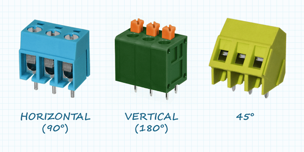
Figure 1: Common wire-entry orientations help optimize panel layout. (Image: allaboutcircuits.com)
Step 3: Master the Materials
The materials used for the conductive and insulating parts of a terminal block are crucial for its performance and longevity.
- Conductive Parts (The Guts): The current-carrying components are typically made from a copper alloy.
- Brass (Copper-Zinc Alloy): This is the most common material. It offers an excellent balance of good electrical conductivity, strong mechanical strength (screws won’t strip easily), and natural corrosion resistance.
- Copper: While pure copper has slightly better conductivity, it is softer and more prone to corrosion. To combat this, copper terminals are almost always tin-plated. This plating improves corrosion resistance and ensures a reliable, low-resistance connection over the long term.
- Insulation / Housing (The Shell): The plastic housing provides insulation and mechanical support. Polyamide (Nylon) is a common choice due to its high dielectric strength, resistance to a wide range of chemicals, and good flammability rating (often UL 94V-0, meaning it is self-extinguishing).
Step 4: Navigate the Global Compliance Maze
This is where that $127,000 mistake was made. Assuming one certification mark covers all regions is a fast track to disaster. Here’s a simplified guide:
- USA (UL): For components inside a control panel (which will itself be listed as a complete assembly under UL 508A), you should be using UL Recognized terminal blocks. These are tested under standard UL 1059. UL Listed products are standalone items approved for field installation. Using a “Listed” block isn’t wrong, but “Recognized” is the correct and specific designation for this application.
- Canada (CSA): Canada has its own standards, primarily CSA C22.2 No. 158. Many products are dual-certified, often indicated by a “cULus” mark, which is the most efficient choice for North American projects.
- Europe (CE): The CE mark is a manufacturer’s self-declaration that the product conforms to EU directives, like the Low Voltage Directive (LVD). It’s based on standards like IEC 60947-7-1. Unlike UL, it doesn’t typically require third-party testing. Always request the manufacturer’s Declaration of Conformity (DoC) to back up the mark.
- United Kingdom (UKCA): Post-Brexit, the UK is phasing out acceptance of the CE mark. For new equipment being placed on the market in Great Britain, the UKCA mark is becoming mandatory.
- China (CCC): The China Compulsory Certificate (CCC) is non-negotiable for many product categories sold or used in China. Terminal blocks fall under this requirement. There is no substitute. If your panel is heading to China, your terminal blocks must have a CCC mark.
| Region | Required Mark(s) | Key Standard(s) | Pro-Tip / Key Consideration |
|---|---|---|---|
| United States | UL Recognized | UL 1059 | “Recognized” is for components inside a larger assembly. “Listed” is for standalone devices. |
| Canada | CSA Certified | CSA C22.2 No. 158 | Look for the cULus mark, which covers both US and Canadian standards. |
| European Union | CE Mark | IEC 60947-7-1/-2 | This is a self-declaration. Always request the manufacturer’s Declaration of Conformity (DoC). |
| United Kingdom | UKCA Mark | BS EN 60947-7-1 | CE is being phased out. For new projects, demand UKCA compliance to be safe. |
| China | CCC Mark | GB/T 14048.7 | Mandatory and strictly enforced by customs. No CCC mark = no entry. |
| Hazardous Areas | ATEX / IECEx / HazLoc | Varies by zone/division | These require specialized, explosion-proof terminal blocks. This is a separate, complex topic. |
Part 3: The Engineer’s Cheat Sheet
To bring this all together, here are two flowcharts to guide your selection process. The first helps you navigate the initial application requirements, and the second dives deeper into selecting the right connection technology.
Part 4: Common Mistakes & Pro-Tips from the Field
Here are some of the most common, real-world mistakes I see engineers make when they choose and install terminal blocks.
- Mistake 1: Ignoring Wire Type. Push-in and spring-clamp terminals work best with single-core wire or stranded wire that has a ferrule crimped on the end. Sticking a bare, stranded wire into a push-in terminal is a common mistake that results in a weak connection, as stray strands can prevent proper clamping. Pro-Tip: Make ferrules a standard part of your panel-building process. They create a solid, secure pin from a stranded wire, ensuring a perfect connection every time.
- Mistake 2: Bad Wire Training. Don’t run wires diagonally across a panel to save a few inches. It looks unprofessional and makes troubleshooting a nightmare. Pro-Tip: Route wires in clean horizontal and vertical lines within your wire ducts. Bend the wire to “train” it into neat right angles before it enters the terminal. This also creates a small amount of slack, or a “service loop,” making it easier to replace a component later.
- Mistake 3: Over-tightening Screws. With screw terminals, there’s a temptation to torque the screw down as hard as possible. This can damage the wire strands or strip the screw threads, leading to a failed connection down the line. Pro-Tip: Use a torque screwdriver set to the manufacturer’s recommended torque value. It guarantees a connection that is tight enough to be secure but not so tight that it causes damage.
- Mistake 4: Forgetting Accessories. Terminal blocks are a system. Don’t forget to order the necessary accessories:
- End Plates/Covers: To insulate the open side of the last block in a row.
- Jumpers/Bridges: To connect adjacent terminals, creating a common bus for power or signals.
- Marking Tags: To label each terminal point. Clear labeling is the hallmark of a professional panel and is invaluable during commissioning and maintenance.
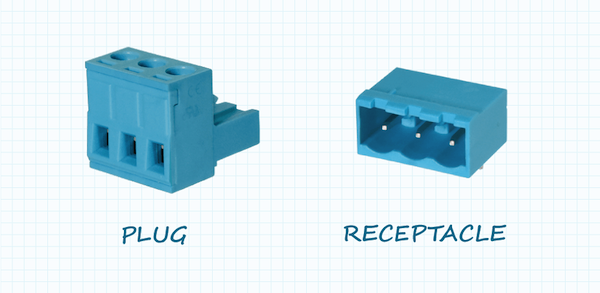
Figure 2: Pluggable terminal blocks allow for quick disconnection without disturbing individual wires. (Image: allaboutcircuits.com)
Comprehensive FAQ Section
Q1: What’s the difference between a terminal block and a barrier strip?
A barrier strip is a type of terminal block, but it’s typically panel-mounted and uses screws to terminate wires, often with ring or spade lugs. A DIN rail terminal block is a more modern, modular component that clips onto a standard rail and offers a variety of connection technologies (screw, spring, push-in).
Q2: When should I absolutely use a ferrule on my wire?
You should use a ferrule on a stranded wire whenever you are inserting it into a push-in or spring-clamp terminal. While some spring clamps can accept bare stranded wire, a ferrule ensures that all strands are contained, providing a more reliable and consistent connection. It’s a cheap insurance policy against future problems.
Q3: Does the brand of terminal block really matter?
Yes. Reputable manufacturers invest heavily in R&D, quality materials, and obtaining and maintaining global certifications. A cheaper, no-name block might look the same, but it may use inferior plastics that crack over time, impure metal alloys with higher resistance, or have fraudulent certification marks. Your connection is only as reliable as its weakest link.
Q4: How do I account for temperature derating?
Most terminal block ratings are based on a standard ambient temperature (e.g., 40°C). If your panel is going into a hotter environment (like a foundry or a desert installation), you must derate the block’s current-carrying capacity. Manufacturers provide derating curves in their datasheets that show how much the maximum allowable current decreases as the ambient temperature increases.
Q5: Can I mix different types of terminal blocks on the same DIN rail?
Yes, as long as they are designed for the same DIN rail profile (e.g., 35mm “top hat”). It’s common to see power distribution blocks, standard feed-through blocks, sensor blocks, and fused terminal blocks all on the same rail. However, ensure that end plates are used to properly separate different groups or voltage levels.
Conclusion: Your New Mandate
Choosing a terminal block is not a trivial task to be delegated or rushed. It’s an engineering decision with significant consequences for the safety, reliability, and cost of your project. By moving from a “what fits?” mindset to a systematic selection process, you transform the terminal block from a potential liability into a cornerstone of a robust and professional control panel.
The next time you start a panel design, don’t leave the terminals until the end. Use this framework. Think about the current, the vibration, the environment, and the final destination. A few extra minutes of diligence during the design phase can save you from a five-figure headache—or worse—down the road. Make getting this right your new mandate. It’s a hallmark of a great engineer.
