THE ROLE OF BUSBAR INSULATORS IN LOW-VOLTAGE & MEDIUM-VOLTAGE SWITCHGEAR SYSTEMS

THE ROLE OF BUSBAR INSULATORS IN LOW-VOLTAGE & MEDIUM-VOLTAGE SWITCHGEAR SYSTEMS?
In the complex, high-stakes world of electrical power distribution, switchgear systems are the critical nerve centers that control, protect, and isolate electrical equipment. The uninterrupted flow of power in our hospitals, data centers, and manufacturing plants depends entirely on the flawless operation of this equipment. While large, dynamic components like circuit breakers and transformers often command attention, the reliability of the entire system frequently rests on one of its smallest and most static components: the busbar insulator. This humble component is the linchpin of switchgear integrity, performing a relentless dual-duty of electrical isolation and mechanical support. A single insulator failure can initiate a chain reaction, leading to a violent arc flash, catastrophic equipment damage, extended operational downtime, and, most critically, severe personnel safety risks.
This article provides an in-depth engineering guide to the busbar insulator. We move beyond a surface-level overview to explore its crucial functions, compare the advanced materials used in its construction, and analyze its distinct applications in both low-voltage (LV) and medium-voltage (MV) systems. We will dissect detailed technical specifications, explore electromagnetic force calculations, review global standards, and outline best practices for selection, installation, and maintenance. Whether you are a system design engineer, a maintenance supervisor, or a technical procurement specialist, this comprehensive analysis will equip you with the knowledge to recognize the busbar insulator not as a commodity component, but as a critical asset for ensuring a safe, efficient, and resilient electrical infrastructure.
The Dual-Function of a Busbar Insulator: More Than Just a Spacer
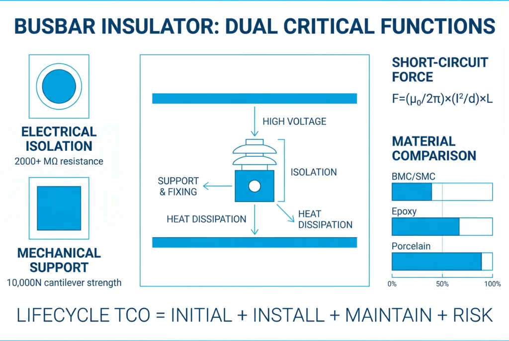
The role of a busbar insulator extends far beyond simply creating space. It performs two critical, interdependent functions: providing robust electrical insulation and delivering uncompromising mechanical support. The synergy between these two functions is what makes it a linchpin of switchgear design.
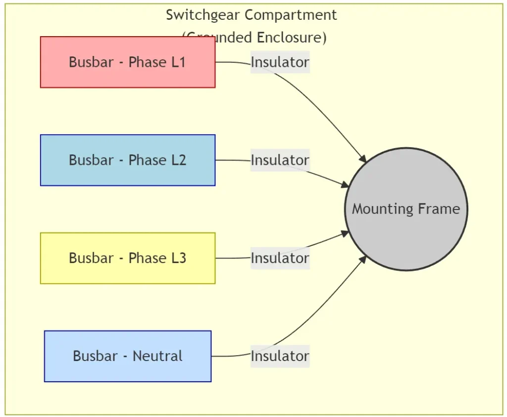
Diagram: Simplified view of busbar insulators providing both mechanical support and electrical isolation for phase and neutral conductors within a grounded metal enclosure.
1. Electrical Insulation and System Safety
At its core, an insulator must prevent the flow of current from the energized busbar to any other conductor or grounded metalwork. It must do this reliably for decades, under varying electrical loads and environmental conditions.
A high-quality insulator achieves this with materials that have high dielectric strength and an insulation resistance that often exceeds 2000 MΩ, even under humid conditions. Its design also incorporates meticulously engineered creepage distance and clearance distance to mitigate failure risks.
- Clearance is the shortest distance through the air between two conductive parts (e.g., busbar to busbar, or busbar to grounded enclosure). It is the primary defense against a dielectric breakdown of air, or “flashover,” caused by high voltage stress. This dimension is strictly dictated by the system’s rated voltage and its Basic Insulation Level (BIL), which defines its ability to withstand transient lightning or switching surges.
- Creepage is the shortest path along the insulator’s surface between two conductive parts. A longer, often convoluted, creepage path is essential for preventing “tracking”—the formation of a conductive carbonized path on the insulator surface. This is particularly critical in environments with high humidity or particulate contamination (dust, chemicals), which are classified by Pollution Degrees (PD) in standards like IEC 60664. An insulator designed for a PD3 (heavy industrial) environment will require a significantly longer creepage distance than one for a PD1 (dry, clean) environment [material://019ad7f6-a061-7c90-84af-c0d200d7be41].
2. Mechanical Support and Structural Integrity
Busbars, made of heavy conductive materials like copper or aluminum, require strong physical support to maintain their position and alignment. A busbar insulator provides this structural backbone. More importantly, during a short-circuit fault, immense and violent electromagnetic forces are generated between the conductors. These forces, which can peak within the first half-cycle of a fault (typically 10 milliseconds), are proportional to the square of the fault current (I²) and inversely proportional to the distance between conductors.
Insulators must possess exceptional mechanical strength—specifically cantilever, tensile, and compressive strength—to withstand these violent forces without fracturing. For example, a heavy-duty low-voltage insulator might be rated for a cantilever load of 10,000N and a tensile strength of 8,000N. This ensures the busbar assembly maintains its structural integrity during the critical moments before a circuit breaker can interrupt the fault [material://019ad7f6-a061-7c90-84af-c0d200d7be41]. The selection of an insulator’s mechanical rating is a precise engineering calculation, not an estimation, to guarantee it is not the weak link in the power system’s chain of defense.
Deep Dive: Calculating Short-Circuit Electromagnetic Forces
To properly specify an insulator’s mechanical strength, engineers must calculate the maximum potential forces exerted on the busbars during a short-circuit event. These forces are dynamic and depend on the system’s prospective fault current, busbar geometry, and physical arrangement.
The peak electromagnetic force between two parallel conductors can be approximated using the following formula:
F_peak = (μ₀ / 2π) * (I_peak² / d) * L
Where:
- F_peak is the peak force in Newtons (N).
- μ₀ is the magnetic permeability of free space (4π × 10⁻⁷ H/m).
- I_peak is the peak asymmetrical short-circuit current in Amperes (A). This is the highest instantaneous current value during the fault.
- d is the distance between the centerlines of the conductors in meters (m).
- L is the length of the conductor between two supporting insulators in meters (m).
graph LR
    subgraph Forces on Parallel Conductors
        direction LR
        A(Busbar 1<br>Current →) -- Repulsive Force ---> B(Busbar 2<br>Current ←)
        C(Busbar 1<br>Current →) -- Attractive Force --- D(Busbar 2<br>Current →)
    end
    linkStyle 0 stroke:red,stroke-width:2px,stroke-dasharray: 5 5
    linkStyle 1 stroke:green,stroke-width:2px,stroke-dasharray: 5 5
Diagram: During a multi-phase fault, currents in adjacent busbars can flow in opposite directions, creating powerful repulsive forces that the insulators must contain.
Practical Calculation Example:
Consider an LV switchgear panel with the following parameters:
- Prospective Symmetrical RMS Fault Current (I_k): 50 kA
- Busbar Spacing (d): 100 mm (0.1 m)
- Insulator Spacing (L): 200 mm (0.2 m)
- Calculate Peak Current (I_peak): The peak current is typically higher than the RMS value due to a DC offset. A common factor for LV systems is 2.2.
- I_peak = 50,000 A * 2.2 = 110,000 A
- Calculate Peak Force (F_peak):
- F_peak = ( (4π × 10⁻⁷) / 2π ) * ( (110,000)² / 0.1 ) * 0.2
- F_peak = (2 × 10⁻⁷) * (1.21 × 10¹⁰ / 0.1) * 0.2
- F_peak = (2 × 10⁻⁷) * (1.21 × 10¹¹) * 0.2
- F_peak ≈ 4840 N (or ~493 kg-force)
This calculation shows that each insulator support must be able to withstand a dynamic cantilever load of at least 4840 Newtons. Therefore, an engineer would select an insulator with a rated cantilever strength well above this value, such as 8,000N or 10,000N, to provide an adequate safety margin. This rigorous approach ensures system survivability under the most extreme conditions.
Material Deep Dive: A Comparative Analysis
The choice of material is the single most important factor determining an insulator’s performance, lifespan, and cost. Different materials are suited for LV and MV applications based on their unique blend of properties. The primary materials used today are advanced polymer composites and traditional ceramics.
| Property | Bulk Molding Compound (BMC) / Sheet Molding Compound (SMC) | Cast Epoxy Resin | Cycloaliphatic Epoxy Resin | Porcelain |
|---|---|---|---|---|
| Primary Application | Low-Voltage (LV) | Medium-Voltage (MV) – Indoor | Medium/High-Voltage (MV/HV) – Outdoor & Demanding Environments | Medium/High-Voltage (MV/HV) – Primarily Outdoor |
| Dielectric Strength | Good (10-20 kV/mm) | Excellent (20-40 kV/mm) | Excellent (22-38 kV/mm) | Very Good (15-35 kV/mm) |
| Mechanical Strength | Good (High impact strength) | Excellent (High tensile & compressive) | Excellent (High flexural strength, fatigue resistance) | Moderate (Brittle, low impact strength) |
| Thermal Resistance | Good (up to 155°C, Class F) | Very Good (up to 130-155°C, Class B/F) | Very Good (up to 130°C, Class B) | Excellent (>1000°C) |
| Track Resistance (CTI) | Excellent (CTI > 600V) | Good to Very Good | Excellent (Hydrophobic, resists tracking) | Good (can be improved with glazes) |
| UV Resistance | Poor (requires coatings) | Poor to Moderate (can yellow) | Excellent | Excellent |
| Water Absorption | Low | Very Low | Extremely Low | Low (if glazed) |
| Manufacturing | Fast cycle, high volume injection/compression molding | Slower vacuum casting process, precise dimensions | Slower vacuum casting, requires specialized molds | High-temperature firing, less precise, labor-intensive |
| Weight | Lightweight | Moderate weight | Moderate weight | Heavy |
| Cost | Low | High | Very High | Moderate to High |
| Key Advantage | Cost-effective, design flexibility, flame retardancy | Superior mechanical performance & dimensional stability | Outstanding UV/weather & tracking resistance | Proven long-term reliability, high compressive strength |
Material Details:
- Bulk Molding Compound (BMC): This is a thermoset composite material made from a mixture of polyester or vinyl ester resin, mineral fillers (like calcium carbonate), and chopped fiberglass reinforcement. Its low cost, rapid molding cycle, and excellent flame-retardant properties (UL 94V-0) make it the dominant material for LV insulators.
- Cast Epoxy Resin: Typically used for MV indoor applications, epoxy resins are two-part systems (a resin and a hardener) that are mixed and cast under a vacuum to eliminate voids. This process results in a dense, mechanically robust insulator with superb dielectric properties and dimensional accuracy. Fillers like silica or alumina are added to improve thermal conductivity and mechanical strength.
- Cycloaliphatic Epoxy Resin: A premium variant of epoxy, this material is specifically formulated for superior performance in outdoor and harsh environments. Its molecular structure provides excellent resistance to UV radiation, weathering, and surface tracking, making it a modern alternative to porcelain for demanding MV and HV applications like in wind turbines or coastal substations.
- Porcelain: The traditional insulator material, made from a blend of clay, kaolin, and quartz fired at high temperatures. It offers exceptional long-term stability, UV resistance, and high compressive strength. However, its brittleness, heavy weight, and susceptibility to damage from impact or vandalism have led to its replacement by polymer composites in many applications, especially indoors and in seismic zones.
Busbar Insulators in Low-Voltage (LV) Switchgear (Below 1kV)
In low-voltage environments (< 1000V), the primary challenges are not extreme electrical stress but rather managing high currents and their associated thermal and mechanical effects within compact enclosures. LV switchgear, such as Motor Control Centers (MCCs), main distribution switchboards, and panelboards, can carry continuous currents of several thousand amperes.
- Materials: LV insulators are almost exclusively made from thermoset composites like Bulk Molding Compound (BMC) or Sheet Molding Compound (SMC). These fiberglass-reinforced polymers offer an optimal balance of dielectric strength, high mechanical stability, superior thermal resistance (typically Class F, 155°C), and essential flame-retardant properties (UL 94V-0) [material://019ad7f6-a061-7c90-84af-c0d200d7be41]. They are lightweight, can be molded into complex shapes with integrated inserts, and are highly cost-effective for mass production compared to traditional porcelain or epoxy [material://019ad7f6-9a37-703b-84d7-24cd2b80764d].
- Types: Common shapes include cylindrical, hexagonal (“standoff”), and multi-pole “comb” style insulators. These are designed for easy and secure installation in compact assemblies, fastened with threaded metal inserts (typically brass for conductivity or steel for strength) that are molded directly into the insulator body.
Design Considerations:A primary challenge in LV systems is managing both thermal rise and massive short-circuit forces. High continuous currents generate significant I²R heating, which must be dissipated to prevent busbar temperatures from exceeding safe limits defined in IEC 61439. While the insulator’s main role is electrical isolation, its material and placement are crucial for thermal management. Advanced designs use thermally conductive (but electrically insulating) material grades and shapes that promote natural air convection to help cool the busbars. Simultaneously, the switchgear’s short-circuit withstand rating (Icw) dictates the insulator’s required mechanical strength, as calculated previously.
mindmap
  root((Thermal Management in Switchgear))
    Heat Sources
      I²R Losses in Busbars
      Connections & Joints
      Circuit Breakers
      Control Components
    Heat Dissipation Strategies
      Passive
        Natural Convection
        Radiation from Surfaces
        Insulator Placement for Airflow
        Thermally Conductive Materials
      Active
        Forced Air (Fans)
        Air Conditioning
        Heat Exchangers
    Monitoring & Prevention
      Thermographic Surveys
      Proper Torque on Connections
      Ventilation Louvers
      Cleanliness
Diagram: Key factors and strategies for thermal management within switchgear enclosures, where insulators play a role in facilitating airflow.
Busbar Insulators in Medium-Voltage (MV) Switchgear (1kV-36kV)
As voltage levels increase into the medium-voltage range (1kV to 36kV), the design considerations for insulators shift dramatically. While fault currents may be lower than in heavy LV systems, the immense electrical stress becomes the dominant engineering challenge.
Heightened Requirements:In MV systems, the insulators must withstand much higher electrical stress, making clearance distances and dielectric properties paramount. Insulators are physically larger and are housed in dedicated, segregated busbar compartments within metal-clad switchgear to ensure safety, contain faults, and prevent fault propagation between sections [material://019ad7f6-9bf3-7660-9f01-c8b853581376]. Partial Discharge (PD) becomes a major concern. PD is a localized dielectric breakdown in a small portion of the insulation system under high voltage stress. While it doesn’t cause immediate failure, continuous PD activity degrades the insulating material over time, creating internal carbonized tracks that eventually lead to a complete dielectric breakdown.
graph TD
    subgraph Electrical Stress on MV Insulator
        A[High Voltage Conductor] --> B(Insulator Body)
        B -- Electric Field Lines --> C[Grounded Base]
        subgraph Sheds Increase Creepage
            direction LR
            D(Flat Surface<br>Short Creepage Path) --- E(Ribbed/Shed Surface<br>Long Creepage Path)
        end
        F[High Stress Concentration] -- at hardware interface --> A
        G[Lower Stress] -- distributed across sheds --> B
    end
    style D fill:#f9f9f9,stroke:#333
    style E fill:#f9f9f9,stroke:#333
    linkStyle 0,1 stroke-width:1px,stroke:blue,fill:none,stroke-dasharray: 2 2;
Diagram: Conceptual illustration of electrical stress distribution and the function of sheds in extending surface creepage distance.
Common Materials and Designs:
- Materials: While high-performance polymers exist, cast epoxy resin and porcelain are the traditional and most trusted materials for MV applications. Epoxy resin offers a superb combination of mechanical strength, low moisture absorption, and the ability to be cast into complex, precise shapes free of internal voids (which mitigates PD risk). For outdoor or high-UV environments, cycloaliphatic epoxy is the material of choice. Porcelain offers outstanding long-term performance and UV resistance, though it is heavier and more brittle [material://019ad7f6-993e-7794-bcb7-394f877713fb].
- Designs: MV insulators are characterized by their “sheds” or “ribs”—a corrugated surface profile. This design is purely functional: it critically increases the creepage distance without increasing the overall insulator height. This makes the component far more resilient to flashovers caused by surface contamination from dust and moisture, a common failure mode at higher voltages, especially in industrial or coastal areas.
graph TD
    subgraph "Typical MV Metal-Clad Switchgear Layout (IEC 62271)"
        A[Busbar Compartment] --- B[Circuit Breaker Compartment]
        B --- C[Cable Compartment]
        A --- D[Low-Voltage / Control Compartment]
        B --- D

        subgraph A
            direction LR
            I1(MV Insulator) -- supports --> BB1(Phase A Busbar)
            I2(MV Insulator) -- supports --> BB2(Phase B Busbar)
            I3(MV Insulator) -- supports --> BB3(Phase C Busbar)
        end
    end
    classDef compartment fill:#e6f3ff,stroke:#005a9e,stroke-width:2px;
    class A,B,C,D compartment;
Diagram: Segregated compartments in MV switchgear, showing insulators housed in a dedicated busbar section for safety and reliability.
Advanced Design Considerations for Different Environments
Standard insulators are designed for typical indoor conditions (e.g., 20°C, <80% humidity, clean air). However, many applications expose switchgear to extreme conditions that require specialized insulator designs and materials.
- High-Altitude Environments: At high altitudes (e.g., >1000m above sea level), air density decreases. This thinner air has a lower dielectric strength, meaning electrical flashovers can occur over shorter distances. To compensate, insulators used at high altitudes must have increased clearance and creepage distances. IEC 62271-1 provides correction factors that must be applied to the insulator’s standard sea-level ratings. An insulator rated for 15kV at sea level might only be suitable for 12kV at 3000m unless its dimensions are increased.
- Marine and High-Pollution Environments: In coastal areas, chemical plants, or mining operations, conductive contaminants like salt, chemicals, or metallic dust can coat insulator surfaces. When combined with moisture, this creates a conductive layer that dramatically reduces the effective creepage distance, leading to tracking and flashovers.
- Solution: Use insulators with highly complex shed profiles (deep, narrow ribs) to create a long, protected creepage path. The material of choice is often cycloaliphatic epoxy or silicone rubber, which have hydrophobic (water-repelling) surfaces that resist the formation of continuous water films.
- High Vibration and Seismic Zones: Applications in railway systems, mobile substations, naval ships, or earthquake-prone regions subject insulators to constant vibration and severe mechanical shock.
- Solution: Brittle materials like porcelain are unsuitable. Epoxy and BMC/SMC composites are preferred due to their superior flexural strength and inherent material damping. Insulators must be specifically designed and tested for fatigue resistance to prevent micro-cracks from forming and propagating over time. For seismic applications, the entire busbar-insulator assembly must be dynamically analyzed to ensure its natural frequency does not align with expected seismic frequencies.
- Extreme Temperature Ranges: Switchgear in desert solar farms or arctic environments can experience ambient temperatures from -50°C to +60°C.
- Solution: The coefficient of thermal expansion (CTE) of the insulator material and its metallic inserts must be closely matched. A significant CTE mismatch can cause the polymer to crack around the insert during extreme temperature cycling. Materials must be certified to retain their mechanical and dielectric properties across the entire operational temperature range without becoming brittle at low temperatures or soft at high temperatures.
Navigating the Standards: A Comparative Overview
Compliance with international and regional standards is non-negotiable. These documents define the design, testing, and performance requirements that ensure safety and interoperability. The primary standards bodies are the International Electrotechnical Commission (IEC), the American National Standards Institute (ANSI)/Institute of Electrical and Electronics Engineers (IEEE), and national bodies like GB/DL in China.
| Standard Body | Primary Switchgear Standard | Key Focus for Insulators | Flammability | Voltage Test Philosophy |
|---|---|---|---|---|
| IEC (Global) | LV: IEC 61439 MV: IEC 62271 | Dielectric properties (Clearance/Creepage), short-circuit withstand, temperature rise, Partial Discharge (PD) testing is critical for MV. | Referenced (e.g., IEC 60695), but less prescriptive than UL. | Power Frequency Withstand, Lightning Impulse (BIL), Switching Impulse. Wet and polluted condition tests are common. |
| ANSI/IEEE (N. America) | LV: UL 891 MV: ANSI C37.20.2 | Mechanical strength (short-circuit), temperature rise, flammability is paramount. | UL 94 is the key standard. V-0 rating is often mandatory, certifying self-extinguishing properties. | Similar to IEC (BIL), but test values and procedures can differ. Historically, PD testing was less emphasized but is now gaining prominence. |
| GB/DL (China) | LV: GB 7251 MV: DL/T 404 | Largely harmonized with IEC standards but may include specific national deviations, particularly for high-altitude applications or grid requirements. | Follows IEC/UL-derived methods. | Follows IEC framework for voltage tests. |
- Key Differences: While largely harmonized, there are crucial differences. North American standards have a strong historical emphasis on fire safety within the enclosure, making the UL 94V-0 rating a strict requirement for most polymer insulators. IEC standards place a greater emphasis on performance under various environmental conditions, with detailed specifications for pollution degrees and mandatory partial discharge testing for MV components to ensure long-term reliability [material://019ad7f6-9c9b-764e-a477-55b26d8b055e]. When sourcing insulators for global projects, it is essential to specify compliance with both IEC and relevant local standards (like UL certification for the North American market).
Testing and Quality Assurance: From Design to Production
To guarantee performance and safety, insulators undergo a rigorous series of tests as defined by standards like IEC 62271 and UL 891. These are divided into type tests (design qualification), routine tests (production quality control), and special tests (customer-specific requirements).
- Type Tests (Design Validation): Performed once on a representative sample to qualify a new insulator design or material. These are destructive and expensive tests.
- Mechanical Tests: Cantilever, tensile, and compressive strength tests are performed until failure to verify the manufacturer’s published load ratings.
- Dielectric Tests: Includes Power-Frequency Withstand (applying a high AC voltage for 60 seconds) and Lightning Impulse Withstand (BIL), which involves applying a very fast, high-voltage pulse (1.2/50 μs waveform) to simulate a lightning strike. These are often done under both dry and wet conditions.
- Temperature Rise Test: Conducted within a sample switchgear assembly to ensure the insulator and its metallic inserts do not contribute to excessive heating under full continuous current.
- Partial Discharge Test (MV only): A critical non-destructive test that measures small electrical discharges in voids within the insulator material. Below a certain voltage, the PD level must be extremely low (e.g., <10 pC), indicating a high-quality, void-free casting.
- Flammability Test: Verification of the material’s UL 94 rating (e.g., V-0, V-1, HB). For a V-0 rating, the material must self-extinguish within 10 seconds after two applications of a flame.
- Environmental Tests: Includes water absorption analysis and thermal cycling (e.g., -40°C to +100°C for 100 cycles) to check for material stability and resistance to cracking.
- Routine Tests (Production Quality Control): Performed on 100% of insulators produced to catch manufacturing defects.
- Visual Inspection: Automated or manual inspection for cracks, voids, chips, surface blemishes, or molding imperfections.
- Dimensional Verification: Checking critical dimensions, especially mounting thread size and location, using gauges or vision systems.
- AC High-Voltage Test (Hi-Pot): A quick power-frequency voltage test (e.g., 5-10kV for 1-5 seconds) applied between the inserts to detect any gross manufacturing defects that compromise the insulation path.
- Special Tests (Client/Application Specific): Agreed upon between the manufacturer and the end-user.
- Seismic/Vibration Test: Shaker table tests to simulate performance in earthquake-prone areas or high-vibration environments.
- Pollution Test: Specific tests in a salt fog or dust chamber to verify performance in highly contaminated environments.
- Material Analysis: Advanced analysis like FTIR (Fourier Transform Infrared Spectroscopy) to verify the polymer composition.
Best Practices: How to Select the Right Busbar Insulator
[…]
- Voltage Rating: The insulator’s rated voltage must be equal to or greater than the maximum system operating voltage. For MV systems, this includes specifying the Basic Insulation Level (BIL) required to withstand transient overvoltages from lightning or switching surges.
- Mechanical Load: Evaluate the static load (weight of the busbars) and, crucially, the dynamic load during a fault. The insulator’s rated cantilever or tensile strength must exceed the calculated maximum electromagnetic forces generated by the system’s prospective short-circuit current, with an appropriate safety margin (e.g., 1.5x – 2.0x).
- Thermal Performance: The insulator material must withstand the maximum operating temperature of the busbar at full load, plus a safety margin. This is typically specified by a thermal class (e.g., Class B: 130°C, Class F: 155°C). The ambient temperature inside the switchgear panel must be factored into this calculation [material://019ad7f6-9af5-7f32-86f9-d2519cb15ac1].
- Environmental Conditions: Consider the operating environment. Will the insulator be exposed to high humidity, conductive dust, corrosive chemicals, or UV radiation? Choose materials and designs with appropriate protections, such as hydrophobic cast epoxy or insulators with long creepage distances for polluted areas [material://019ad7f6-9a37-703b-84d7-24cd2b80764d].
- Compliance and Certification: Always select insulators that are type-tested and certified by a recognized authority (e.g., UL, KEMA) to meet the relevant industry standards for your region and application (e.g., IEC, UL, ANSI). Always request full type test reports from the manufacturer for review.
- Form Factor and Mounting: The physical shape, size, and mounting mechanism (e.g., thread size of inserts) must fit the design constraints of your switchgear enclosure and busbar configuration. Ensure adequate clearance is maintained after installation.
Installation Best Practices and Common Mistakes
Even a perfectly specified insulator can fail if installed incorrectly. Proper installation is crucial for long-term reliability.
Best Practices:
- Torque Control: Always use a calibrated torque wrench to tighten fasteners. Over-tightening can induce micro-cracks and stress points in the insulator body, leading to premature mechanical failure. Under-tightening can result in loose connections, causing vibration, arcing, and thermal hot spots. Refer to the manufacturer’s recommended torque values for the specific insulator and bolt size.
- Surface Cleanliness: Ensure the insulator surface is perfectly clean and dry before and during installation. Any contaminants like grease, fingerprints, or construction dust can compromise creepage distance and become a point for tracking initiation.
- Proper Alignment: Ensure busbars are properly aligned and not forced into place. Misalignment puts continuous mechanical stress on insulators, leading to long-term fatigue.
- Use Correct Hardware: Always use the specified grade and size of bolts, nuts, and washers. Hardened flat washers are essential to distribute the clamping force evenly over the insulator’s mounting surface and prevent localized stress.
Common Mistakes to Avoid:
[…]
Failure Modes and Root Cause Analysis
Understanding why insulators fail is key to improving system design and preventing future incidents. Failures are broadly categorized as mechanical or electrical.
| Failure Mode | Description | Common Root Causes | Prevention |
|---|---|---|---|
| Mechanical Fracture | The insulator body cracks, shatters, or breaks away from its insert. | Short-circuit force exceeding rating; over-tightening during installation; vibration fatigue; impact damage during handling; CTE mismatch. | Correctly calculate fault forces and apply a safety factor; use a torque wrench; install vibration dampeners in relevant applications; proper handling procedures. |
| Electrical Flashover | An arc jumps across the surface or through the air between conductive parts. | Inadequate clearance/creepage for the voltage/environment; severe surface contamination; high humidity/condensation; transient overvoltage (lightning). | Select insulators based on voltage AND pollution degree; implement a cleaning schedule; install surge arresters in the system. |
| Surface Tracking | A permanent, conductive carbon path forms on the insulator surface, eventually causing a short. | Prolonged surface discharge due to contamination and moisture, combined with a material with poor tracking resistance. | Select materials with a high Comparative Tracking Index (CTI > 600V); use ribbed/shed designs; periodic inspection and cleaning. |
| Thermal Degradation | The material becomes brittle, discolored (often darkened), or deformed from heat. | Continuous operation above the material’s thermal rating (e.g., 155°C); hot spots from loose connections heating the insulator’s metal insert. | Ensure proper panel ventilation; perform regular thermographic scans to detect hot spots; verify all bolted connections are torqued correctly. |
graph TD
    A[Insulator Failure Event] --> B{Initial Assessment};
    B --> C[Mechanical Fracture?] & D[Electrical Fault?];
    C --> E[Check torque records & installation photos];
    C --> F[Compare calculated max fault current to insulator rating];
    D --> G{Flashover or Tracking?};
    G -- Flashover --> H[Check environmental data (humidity, pollution)];
    G -- Flashover --> H2[Verify clearance distances match design];
    G -- Tracking --> I[Analyze material for carbon paths (CTI rating)];
    G -- Tracking --> I2[Check for surface contamination];
    E & F & H & H2 & I & I2 --> K[Determine Root Cause];
    K --> L[Implement Corrective Actions: e.g., Update Spec, Revise PM, Training];
Diagram: A more detailed flowchart for root cause analysis of an insulator failure.
Economic Analysis and Lifecycle Cost (TCO)
Choosing an insulator based on the lowest initial purchase price is a common but dangerous mistake. A true economic analysis considers the Total Cost of Ownership (TCO), which encompasses all costs over the component’s entire service life.
TCO = Initial Cost + Installation Cost + Maintenance Cost + Risk Cost
- Initial Cost: The purchase price of the insulator.
- Installation Cost: Labor and equipment for installation.
- Maintenance Cost: The cost of planned inspections, cleaning, and testing over a 20-30 year lifespan.
- Risk Cost: This is the most critical and often ignored factor. It is the potential cost of failure, calculated as: (Probability of Failure) x (Cost of Failure). The cost of failure includes:
- Cost of equipment replacement (busbars, breakers, entire switchgear sections).
- Cost of unplanned downtime (lost production, penalties).
- Cost of a potential arc flash incident (injury, litigation, insurance hikes).
A high-quality, certified insulator from a reputable manufacturer may have a 20% higher initial cost, but its vastly lower probability of failure drastically reduces the “Risk Cost,” making its TCO much lower than that of a cheaper, uncertified alternative.
flowchart LR
    subgraph Lifecycle Management
        A[1. Specification<br>Voltage, Current, Environment] --> B[2. Sourcing<br>Reputable Manufacturer, Certs]
        B --> C[3. Installation<br>Torque Wrench, Cleanliness]
        C --> D[4. Operation & Maintenance<br>IR Scan, Cleaning]
        D --> E{End of Life?}
        E -- No --> D
        E -- Yes --> F[5. Decommissioning<br>& Replacement]
    end
    A -- TCO Analysis --> B
Diagram: The insulator lifecycle process, where TCO analysis informs sourcing, and proactive maintenance ensures reliability.
Maintenance and Inspection Guidelines
Regular, proactive maintenance is essential for ensuring the continued reliability of the switchgear assembly. All maintenance must be performed with the equipment fully de-energized, tested for absence of voltage, and locked/tagged out (LOTO).
| Activity | Frequency (Clean Environment) | Frequency (Harsh Environment) | Method/Tools | Purpose |
|---|---|---|---|---|
| Visual Inspection | 1-2 Years | 6-12 Months | Bright flashlight, mirror | Check for cracks, chips, discoloration, dust buildup, signs of tracking. |
| Cleaning | As needed (5+ years) | 1-2 Years | Lint-free cloth, approved solvent (e.g., isopropyl alcohol) | Removes conductive contaminants to restore full creepage distance and prevent tracking. |
| Thermographic Survey | 1 Year | 6 Months | Calibrated IR camera | Identify high-resistance connections (hot spots) at the insulator’s metal inserts before they fail. |
| Torque Check | 3-5 Years | 1-2 Years | Calibrated torque wrench | Ensure bolted connections have not loosened due to vibration or thermal cycling. |
| Insulation Resistance Test | 3-5 Years | 2-3 Years | Megohmmeter (“Megger”) | Trend the quality of the insulation over time. A sharp drop indicates moisture or severe contamination. |
Future Trends and Innovations
The field of busbar insulators is evolving with advances in material science, sensing technology, and smart grid integration.
- Smart Insulators: The next generation of critical insulators will feature embedded sensors. Fiber-optic sensors can monitor temperature and mechanical strain in real-time without introducing any conductive elements. Embedded RFID tags can store manufacturing data, installation dates, and maintenance records, accessible with a simple scan. This data feeds into digital twin models and predictive maintenance platforms, allowing operators to anticipate failures.
- Nanocomposite Materials: Research is focused on polymer dielectrics infused with nano-scale fillers (like silica, alumina, or boron nitride). These nanocomposites promise revolutionary properties: significantly improved thermal conductivity for better heat dissipation from busbars, enhanced mechanical strength in a more compact form factor, and superior resistance to partial discharge and surface tracking.
- Self-Cleaning and Functional Surfaces: Inspired by the “lotus effect,” new surface coatings and material treatments are being developed that are super-hydrophobic and oleophobic (oil-repelling). These surfaces actively prevent water from forming continuous films and stop dust and pollution from adhering, drastically reducing cleaning maintenance and improving flashover performance in even the most contaminated environments.
- Additive Manufacturing (3D Printing): While not yet viable for mass production due to speed and material limitations, 3D printing with high-performance polymers is revolutionizing prototyping. It allows for the rapid creation of highly complex, functionally-optimized insulator geometries. In the future, it may enable the printing of functionally graded materials, where the material properties (e.g., mechanical strength vs. dielectric constant) can be varied throughout the insulator’s body for ultimate performance.
Case Studies: Real-World Applications
Case Study 1: Data Center LV Switchgear
- Challenge: A hyperscale data center required a 4000A LV switchgear with a 100kA short-circuit rating. Key requirements were extreme reliability (99.999% uptime), a compact footprint to maximize server space, and zero risk of fire propagation (UL 94V-0).
- Solution: High-strength hexagonal standoff insulators made from a fiberglass-reinforced BMC were selected. These insulators provided a cantilever strength of over 10,000N to withstand the immense fault forces and were certified UL 94V-0. Their compact design allowed for tight busbar spacing, minimizing the overall switchgear footprint while maintaining safety margins.
Case Study 2: Wind Turbine MV Switchgear
- Challenge: The nacelle of a multi-megawatt offshore wind turbine houses 33kV switchgear. The environment involves constant vibration, extreme temperature swings (-30°C to +50°C), high humidity, and corrosive salt spray. Reliability is paramount as maintenance is exceptionally difficult and costly.
- Solution: Custom-cast cycloaliphatic epoxy resin insulators were used. The epoxy material was specifically formulated for superior mechanical damping and fatigue resistance against constant vibration. Its hydrophobic properties and high tracking resistance ensured reliable performance despite condensation and salt contamination, preventing flashovers and maximizing turbine uptime.
Case Study 3: Aluminum Smelter Power Rectification
- Challenge: The rectifier station for an aluminum smelter uses massive LV busbars carrying currents in excess of 20,000A. The environment is characterized by intense magnetic fields, high ambient temperatures, and highly corrosive and conductive alumina dust.
- Solution: Extra-large, high-strength porcelain standoff insulators were chosen. While polymers are common in LV, the extreme ambient heat and chemical environment favored the thermal stability and chemical inertness of porcelain. Their massive size provided the necessary mechanical strength to handle the huge electromagnetic forces and high busbar weight. A strict, frequent cleaning schedule was implemented to manage the conductive dust.
Case Study 4: High-Speed Rail Traction Substation
- Challenge: A 25kV AC traction power substation is located adjacent to the railway line. The equipment is subjected to extreme shock and vibration from passing trains, as well as brake dust contamination and wide temperature variations.
- Solution: A fiberglass-reinforced polymer composite insulator with a silicone rubber outer sheath was selected. The fiberglass core provided the high mechanical strength and fatigue resistance needed to withstand the vibration. The outer silicone rubber housing provided excellent hydrophobic, self-cleaning properties to combat the conductive brake dust and environmental pollution, ensuring reliable power to the overhead lines.
Conclusion: The Engineered Core of Electrical Safety and Reliability
While often overshadowed by larger, more dynamic components, the busbar insulator is an indispensable, highly engineered cornerstone of any safe, reliable, and durable switchgear system. It is a testament to the fusion of material science and electrical engineering, performing the dual roles of electrical isolation and mechanical support with silent precision for decades.
From material science and electromagnetic force calculations to global standards compliance and proactive maintenance, every stage of an insulator’s lifecycle is a critical engineering decision. An under-specified or poorly installed insulator is a latent vulnerability, a ticking time bomb within the electrical system. Conversely, a correctly specified, high-quality, certified component is a long-term investment in system integrity and operational resilience. As power demands grow and systems become more complex, the role of the humble busbar insulator only becomes more critical. Its proper selection, installation, and care are not afterthoughts—they are fundamental requirements for protecting multi-million dollar electrical assets, maximizing operational uptime, and, most importantly, ensuring the safety of all personnel who work with or near high-power electrical equipment.
