
Low Voltage Busbar Insulators in Motor Control Centers: Application Guide


Understanding Low Voltage Busbar Insulators in Motor Control Centers
Motor Control Centers (MCCs) serve as the backbone of industrial electrical distribution systems, housing multiple motor starters and control equipment in a centralized location. Within these complex assemblies, low voltage busbar insulators play a critical role in ensuring safe, reliable power distribution while maintaining proper electrical isolation between phases and ground. As electrical systems become increasingly compact and power densities rise, the selection and application of appropriate busbar insulators becomes paramount for system safety and longevity.
Willele Electric specializes in manufacturing high-performance heat shrink tube solutions for electrical equipment, including advanced busbar insulator systems designed specifically for motor control center applications. Our products meet the demanding requirements of modern industrial environments where reliability, safety, and efficiency are non-negotiable.
Key Functions of Busbar Insulators in MCCs
Electrical Isolation and Safety
Low voltage busbar insulators provide essential electrical isolation between current-carrying busbars and grounded enclosure components. In motor control centers operating at voltages up to 1000V AC, maintaining proper clearances and insulation integrity prevents arc flash incidents, ground faults, and equipment damage. The insulators create physical barriers that ensure safe operation even under fault conditions.
Mechanical Support and Vibration Damping
Beyond electrical insulation, these components provide robust mechanical support for heavy copper or aluminum busbars. In MCC environments where motor starting creates significant vibration and electromagnetic forces, insulators absorb shock loads and prevent busbar movement that could lead to connection failures or short circuits.
Environmental Protection
Quality busbar insulators protect connection points from environmental contaminants including dust, moisture, and chemical vapors common in industrial settings. Heat shrink insulator designs offer superior sealing properties, creating a protective envelope around critical electrical interfaces.
Material Technologies for Busbar Insulators
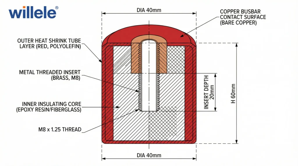
Comparative Analysis of Insulator Materials
| Material Type | Dielectric Strength | Temperature Rating | Flame Resistance | Chemical Resistance | Typical Applications |
|---|---|---|---|---|---|
| Cross-linked Polyolefin | 20-25 kV/mm | -55°C to +135°C | Self-extinguishing | Excellent | General purpose MCCs |
| Silicone Rubber | 18-22 kV/mm | -60°C to +200°C | Excellent | Good | High-temperature environments |
| Polyester (PET) | 22-28 kV/mm | -40°C to +150°C | Very good | Moderate | Standard duty applications |
| Fluoropolymer (PVDF) | 25-30 kV/mm | -55°C to +175°C | Outstanding | Superior | Chemical processing facilities |
| Epoxy Resin | 16-20 kV/mm | -40°C to +155°C | Very good | Excellent | Permanent installations |
Heat Shrink Technology Advantages
Heat shrink busbar insulators represent the current industry standard for motor control center applications. When heated, these materials shrink to form a tight, conforming seal around busbar connections and support points. Willele Electric’s heat shrink solutions offer:
- Superior dielectric performance with consistent wall thickness after shrinking
- Moisture resistance through seamless construction eliminating ingress points
- Mechanical durability maintaining properties through thermal cycling
- Installation efficiency reducing labor costs compared to wrapped tape systems
- Visual inspection capability allowing quick verification of coverage integrity
Technical Specifications and Voltage Ratings
Standard Voltage Classes for MCC Applications
| Voltage Class | Rated Voltage | Impulse Withstand | Minimum Creepage Distance | Recommended Insulator Thickness |
|---|---|---|---|---|
| 230V / 400V | 690V AC | 6 kV | 12 mm | 1.5 mm |
| 480V / 277V | 600V AC | 6 kV | 10 mm | 1.5 mm |
| 690V / 400V | 1000V AC | 8 kV | 16 mm | 2.0 mm |
| DC Systems | 1500V DC | 10 kV | 20 mm | 2.5 mm |
Critical Performance Parameters
Dielectric Withstand Voltage: Low voltage busbar insulators in motor control centers must withstand routine high-potential testing at 2.5 times rated voltage plus 1000V for one minute without breakdown. Willele products typically exceed these requirements with safety margins of 150-200%.
Tracking Resistance: In accordance with IEC 60112 standards, insulators should demonstrate CTI (Comparative Tracking Index) values of at least 600V for pollution degree 2 environments typical of enclosed MCCs.
Temperature Index: The Relative Thermal Index (RTI) should match or exceed the maximum operating temperature of the busbar system, typically requiring materials rated for continuous operation at 130°C minimum.
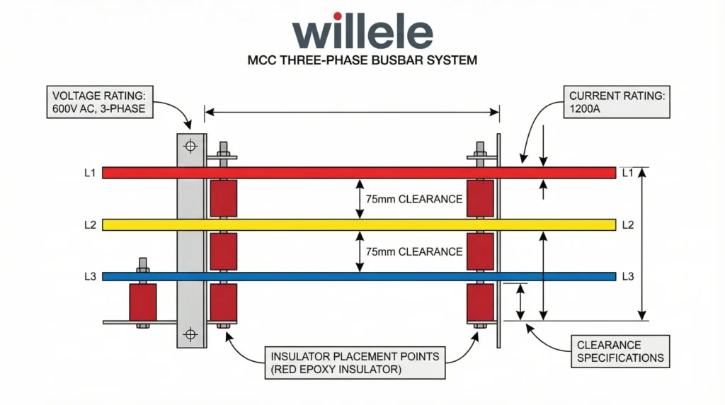
Selection Criteria for MCC Busbar Insulators
Current Carrying Capacity Considerations
The physical size and thermal mass of busbar insulators directly impacts the current-carrying capacity of the busbar system. When selecting insulators:
- Verify temperature rise under maximum load conditions does not exceed 30°C above ambient
- Calculate contact area ensuring sufficient surface for heat dissipation
- Consider thermal conductivity of insulator material in heat transfer calculations
- Plan spacing between insulators to allow natural convection cooling
Environmental Rating Requirements
Motor control centers operate in diverse industrial environments requiring appropriate insulator specifications:
Indoor General Purpose (IP20-IP41): Standard cross-linked polyolefin heat shrink insulators provide adequate protection for climate-controlled electrical rooms.
Industrial Environments (IP54-IP65): Enhanced sealing with dual-wall heat shrink construction protects against dust and moisture ingress in manufacturing facilities.
Harsh Conditions (IP66-IP67): Specialized fluoropolymer materials resist chemicals, oils, and sustained water exposure in process industries.
Outdoor Installations: UV-stabilized formulations prevent degradation from sunlight exposure when MCCs are located in outdoor enclosures.
Installation Best Practices
Pre-Installation Preparation
- Surface cleaning: Remove all oxidation, oils, and contaminants from busbar surfaces using appropriate solvents
- Dimensional verification: Confirm busbar dimensions match insulator specifications with 10-15% shrink allowance
- Component inspection: Examine insulators for damage, proper size markings, and material certification
- Tool preparation: Ensure heat guns or ovens are calibrated to manufacturer-specified temperatures
Heat Shrink Application Procedure
Step 1 – Positioning: Slide heat shrink insulator over busbar connection or support point, centering the component with equal overhang on both sides.
Step 2 – Heat Application: Apply uniform heat using industrial heat gun at 120-150°C, rotating the busbar to ensure even shrinkage. Avoid overheating which can degrade material properties.
Step 3 – Inspection: Verify complete shrinkage with no air pockets, wrinkles, or gaps. The insulator should conform tightly to busbar profile.
Step 4 – Cooling: Allow natural cooling for 5-10 minutes before mechanical stress or electrical energization.
Quality Assurance Testing
Post-installation verification ensures proper insulator performance:
- Visual inspection: 100% coverage verification with no exposed conductor
- Mechanical test: Gentle torque application confirming secure fit without rotation
- Dielectric test: High-potential testing at specified voltages before energization
- Documentation: Record insulator specifications, installation date, and test results
Common Applications in Motor Control Centers
Main Bus Insulation
The primary horizontal or vertical busbars distributing power throughout the MCC require insulators at regular support intervals. Typical spacing ranges from 600-900mm depending on busbar size and fault current ratings. Willele’s heavy-duty heat shrink insulators provide both electrical isolation and mechanical support for these critical conductors.
Branch Circuit Connections
Individual motor starter connections to the main busbar system need insulation at tap-off points. These applications demand insulators capable of accommodating different busbar sizes and angles while maintaining full dielectric strength across the transition.
Phase Barriers and Segregation
Low voltage busbar insulators create phase-to-phase barriers in compact MCC designs where space constraints limit physical clearances. Properly rated insulators allow reduced spacing while maintaining safety margins required by electrical codes.
Ground Bus Isolation
While ground busbars are intentionally grounded, insulator mounting hardware requires isolation from live components. Specialized insulators with metal inserts provide mechanical attachment points while maintaining electrical separation.
Maintenance and Inspection Guidelines
Routine Visual Inspections
Quarterly inspections should examine:
- Surface condition: Checking for cracks, discoloration, or degradation
- Contamination: Identifying dust accumulation, moisture, or chemical residues
- Mechanical integrity: Verifying tight fit without looseness or displacement
- Connection points: Examining adjacent busbar connections for overheating signs
Thermographic Analysis
Annual infrared scanning identifies thermal anomalies indicating:
- Degraded insulator materials causing increased thermal resistance
- Poor contact surfaces requiring maintenance
- Overloaded circuits requiring system upgrades
- Imbalanced phases creating localized heating
Predictive Maintenance Strategies
Implementing condition-based monitoring extends insulator service life:
- Temperature trending: Tracking maximum operating temperatures over time
- Load profiling: Correlating thermal performance with electrical loading
- Environmental monitoring: Recording humidity, contamination, and ambient conditions
- Replacement planning: Scheduling proactive upgrades based on degradation rates
Compliance and Standards
International Standards
Low voltage busbar insulators in motor control centers must comply with:
- IEC 61439 series: Low-voltage switchgear and controlgear assemblies
- IEC 60947-1: General rules for low-voltage switchgear
- UL 845: Motor control centers (North American markets)
- IEC 60529: Ingress protection ratings
- IEC 60664-1: Insulation coordination for low-voltage systems
Certification Requirements
Willele Electric maintains comprehensive third-party certifications:
- Material flammability ratings (UL94 V-0)
- RoHS compliance for environmental safety
- REACH registration for European markets
- ISO 9001 quality management system certification
- Product-specific approvals from major certification bodies
Future Trends in MCC Insulator Technology
Nanotechnology Enhancements
Advanced formulations incorporating nanoparticles improve dielectric strength by 20-30% while reducing material thickness. This enables more compact MCC designs without compromising safety margins.
Smart Insulator Systems
Emerging technologies integrate temperature sensors and RFID tags within insulator structures, enabling real-time condition monitoring and predictive maintenance capabilities.
Sustainable Materials
Development of bio-based polymer insulators reduces environmental impact while maintaining required electrical and mechanical performance specifications.
Frequently Asked Questions
Q: What is the typical service life of heat shrink busbar insulators in motor control centers?
A: Properly installed heat shrink busbar insulators typically provide 20-30 years of service life in standard industrial environments. Service life depends on operating temperature, electrical stress, and environmental conditions. Regular inspections and maintenance can extend operational life significantly.
Q: Can I reuse heat shrink insulators if I need to modify busbar connections?
A: No, heat shrink insulators cannot be reused once installed. The shrinking process permanently alters the material structure, and attempting to remove and reinstall compromises electrical and mechanical properties. Always use new insulators for any modifications or repairs.
Q: How do I determine the correct insulator size for my busbar dimensions?
A: Measure the maximum busbar width and thickness, then select an insulator with an unshrunk internal diameter 30-50% larger than these dimensions. Heat shrink insulators typically have a 2:1 or 3:1 shrink ratio. Willele provides detailed sizing charts for all product lines to simplify selection.
Q: What causes premature insulator failure in MCCs?
A: Common failure modes include thermal degradation from excessive busbar temperatures, mechanical damage during installation or maintenance, chemical attack from environmental contaminants, and electrical tracking from surface contamination. Proper selection, installation, and maintenance prevent most failures.
Q: Are there special considerations for DC motor control centers versus AC systems?
A: Yes, DC systems require enhanced insulation due to electrolytic corrosion potential and different voltage stress patterns. DC-rated insulators need higher tracking resistance and are typically specified with 50% higher voltage margins than equivalent AC applications.
Q: How does ambient temperature affect insulator selection?
A: Operating temperatures above 40°C ambient require insulators with higher temperature ratings. For every 10°C increase in ambient temperature, insulator current capacity decreases approximately 5-7%. In high-temperature environments, specify insulators rated for 150°C or higher continuous operation.
Conclusion
Low voltage busbar insulators represent critical safety and reliability components in motor control center designs. Proper selection based on voltage class, environmental conditions, and mechanical requirements ensures long-term system performance. Willele Electric’s advanced heat shrink insulator technology provides superior electrical isolation, mechanical support, and environmental protection for demanding industrial applications.
For technical specifications, custom solutions, or application engineering support, contact Willele Electric’s technical team. Our expertise in heat shrink technology and comprehensive product range supports motor control center manufacturers and system integrators worldwide in delivering safe, reliable electrical distribution systems.
