
How to Calculate Creepage Distance for Busbar Insulators

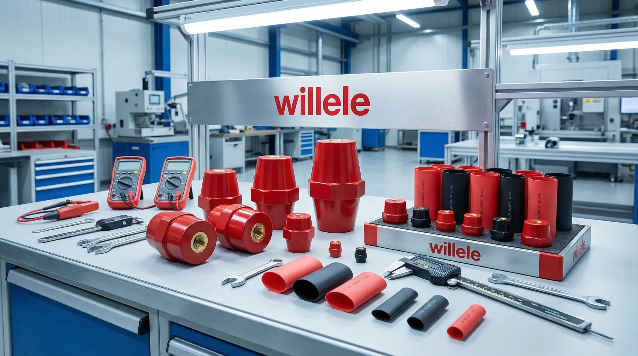
In the high-stakes world of industrial electrical design, precision is not just a preference—it is a safety requirement. For engineers and procurement professionals sourcing components for power distribution systems, understanding how to calculate creepage distance for busbar insulators is fundamental to preventing electrical failure, tracking, and potential fire hazards.
At Willele Electric, we understand that the reliability of your equipment depends on the quality of its insulation. As a premier B2B manufacturer specializing in electric equipment and high-performance heat shrink tubes, we provide the technical insights necessary to optimize your busbar systems for safety and longevity.
What is Creepage Distance and Why Does It Matter?
Before diving into the calculations, it is essential to distinguish between two critical concepts in high-voltage design: Clearance and Creepage Distance.
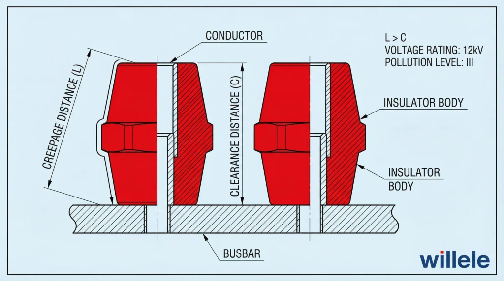
- Clearance is the shortest distance between two conductive parts measured through the air.
- Creepage Distance is the shortest distance between two conductive parts measured along the surface of the insulation material.
For busbar insulators, creepage is often the more critical factor. Over time, dust, moisture, and pollutants can accumulate on the surface of an insulator. These contaminants can create a conductive path, leading to “tracking”—a process where current leaks across the surface, potentially causing a flashover. Calculating the correct creepage distance ensures that the insulation surface is long enough to prevent this tracking, even under adverse environmental conditions.
Key Factors Influencing Creepage Calculation
To accurately calculate the required creepage distance, you must evaluate three primary variables defined by international standards such as IEC 60664-1 and UL 840.
1. Working Voltage (RMS)
The working voltage is the highest RMS (Root Mean Square) voltage that may occur across the insulation when the equipment is operating at its rated voltage. Higher voltages require longer creepage paths to prevent surface flashover.
2. Pollution Degree
The environment where the busbar insulator is installed dictates the pollution degree. The more conductive contaminants present, the longer the creepage distance must be.
- Pollution Degree 1: No pollution or only dry, non-conductive pollution occurs. (e.g., sealed clean rooms).
- Pollution Degree 2: Only non-conductive pollution occurs, except that occasionally a temporary conductivity caused by condensation is to be expected. (e.g., typical office or household environments).
- Pollution Degree 3: Conductive pollution occurs, or dry, non-conductive pollution occurs which becomes conductive due to condensation. (e.g., typical industrial environments, boiler rooms).
- Pollution Degree 4: Continuous conductivity occurs due to conductive dust, rain, or snow. (e.g., outdoor environments).
3. Comparative Tracking Index (CTI) / Material Group
The CTI is a measure of the electrical breakdown (tracking) properties of the insulating material. Materials are grouped based on their CTI values:
- Material Group I: CTI ≥ 600
- Material Group II: 400 ≤ CTI < 600
- Material Group IIIa: 175 ≤ CTI < 400
- Material Group IIIb: 100 ≤ CTI < 175
High-quality insulators, such as those manufactured using Willele Electric’s advanced polymer formulations, often fall into Group I or II, allowing for shorter creepage distances compared to lower-grade materials.
Step-by-Step Guide: How to Calculate Creepage Distance
Calculating the required creepage distance is a systematic process. Follow these steps to ensure compliance with IEC and UL standards.
Step 1: Determine the System Voltage
Identify the phase-to-phase or phase-to-ground voltage of your busbar system. For example, a standard industrial setup might operate at 400V or 690V.
Step 2: Identify the Pollution Degree
Assess the installation environment. For most industrial busbar applications within switchgear or control panels, Pollution Degree 3 is the standard assumption unless the enclosure is hermetically sealed or climate-controlled.
Step 3: Select the Insulator Material Group
Consult the datasheet of your busbar insulator or heat shrink tube. If you are using Willele Electric insulation products, refer to our technical specifications for the CTI value. A higher CTI (Group I) is preferable for compact designs.
Step 4: Consult the Standard Tables
Using the data from steps 1-3, refer to the tables provided in IEC 60664-1.
Example Calculation:
- System: 3-Phase 400V
- Environment: Industrial Factory (Pollution Degree 3)
- Material: Standard Glass-Reinforced Polyester (Group IIIa)
Looking at the IEC standard table (simplified below), for 400V in Pollution Degree 3 with Material Group IIIa, the required creepage distance might be 6.3mm. However, if you upgrade to a Material Group I insulator, the requirement might drop to 4.0mm, saving valuable space.
Step 5: Measure the Physical Path
Measure the surface contour of the insulator. If the insulator has ribs or skirts (convolutions), the path follows the contour of these ribs. This is why busbar insulators often have a “ribbed” design—it increases the surface distance without increasing the direct linear distance between conductors.
Reference Tables for Busbar Insulator Selection
To assist in your preliminary calculations, refer to the following data tables based on general IEC standards. Note: Always consult the specific standard relevant to your region and application for final certification.
Table 1: Material Group Classifications
| Material Group | CTI Value (Volts) | Characteristics |
|---|---|---|
| Group I | 600 ≤ CTI | Excellent tracking resistance (e.g., High-grade Ceramics, Specific Polymers) |
| Group II | 400 ≤ CTI < 600 | Good tracking resistance |
| Group IIIa | 175 ≤ CTI < 400 | Moderate tracking resistance (Common plastics) |
| Group IIIb | 100 ≤ CTI < 175 | Low tracking resistance |
Table 2: Minimum Creepage Distances (mm) – Simplified IEC 60664-1
| Voltage (RMS) | Pollution Degree 1 | Pollution Degree 2 | Pollution Degree 3 (Group I) | Pollution Degree 3 (Group II) | Pollution Degree 3 (Group III) |
|---|---|---|---|---|---|
| 250V | 0.6 | 1.8 | 3.2 | 3.6 | 4.0 |
| 400V | 1.0 | 2.8 | 5.0 | 5.6 | 6.3 |
| 630V | 1.8 | 4.0 | 8.0 | 9.0 | 10.0 |
| 1000V | 3.2 | 6.3 | 12.5 | 14.0 | 16.0 |
The Role of Heat Shrink Tubes in Creepage Management
One of the most effective ways to manage creepage distance in tight spaces is the application of busbar heat shrink tubes.
Willele Electric specializes in manufacturing high-dielectric strength heat shrink tubing. By applying these tubes to the busbars, you effectively modify the surface characteristics of the system. While the physical distance between bars remains the same, the insulation tubing provides a barrier that resists tracking and environmental contamination, effectively allowing for tighter spacing in switchgear cabinets.
Common Mistakes to Avoid
Even seasoned engineers can make errors when calculating or applying creepage rules. Here are common pitfalls to avoid:
- Ignoring Rib Geometry: When measuring creepage on a ribbed insulator, any groove less than 1mm wide is usually treated as non-existent by standards (the path “skips” over it). Ensure your ribs are wide enough to count toward the total distance.
- Confusing Clearance and Creepage: Never use the clearance distance requirement for creepage. Creepage is almost always a larger value.
- Overlooking Altitude: At high altitudes (over 2000m), air density decreases, which affects dielectric strength. While this primarily impacts clearance, it requires a holistic review of the insulation system.
- Neglecting Maintenance: A calculation is based on the assumed pollution degree. If a “clean” room is left dirty, the effective pollution degree rises, rendering the original calculation void and the system unsafe.
Conclusion
Calculating the creepage distance for busbar insulators is a critical step in ensuring the safety and compliance of electrical assemblies. By understanding the interplay between voltage, pollution degree, and material CTI, you can select the right components for your application.
At Willele Electric, we are committed to providing high-quality insulation solutions that meet rigorous global standards. Whether you need precision-molded insulators or industrial-grade heat shrink tubes, our team is ready to support your engineering needs.
Frequently Asked Questions (FAQ)
1. Can creepage distance be less than clearance distance?
No. By definition, the creepage distance (surface path) cannot be shorter than the clearance distance (direct air path). In the best-case scenario (a flat surface), creepage equals clearance, but it is usually longer.
2. How can I reduce the required creepage distance in my design?
You can reduce the required distance by:
- Using insulating materials with a higher CTI (Material Group I).
- Reducing the Pollution Degree of the environment (e.g., using a sealed enclosure).
- Applying conformal coating or potting to the assembly.
3. Does heat shrink tubing affect creepage distance calculations?
Yes. High-quality heat shrink tubing from manufacturers like Willele Electric improves the dielectric strength and tracking resistance of the busbar assembly. It prevents direct exposure to pollution, often allowing for reduced spacing between phases compared to bare busbars.
4. What is the difference between CTI and PTI?
CTI (Comparative Tracking Index) is the voltage at which the material can withstand 50 drops of electrolyte without tracking. PTI (Proof Tracking Index) is a pass/fail test at a specific voltage. CTI is generally used for material classification in design calculations.
5. Why do busbar insulators have ridges or skirts?
The ridges (or skirts) are designed to increase the surface area distance (creepage path) without increasing the overall height or length of the insulator. They also help break the path of water or conductive dust accumulation.
6. Which standard should I follow: IEC or UL?
This depends on your target market. IEC 60664 is the primary standard for Europe and international markets, while UL 840 is standard for North America. While the physics are the same, the specific tables and test methods may differ slightly.
7. What happens if the creepage distance is too short?
If the distance is insufficient, “tracking” can occur. This is the formation of a conductive path across the surface of the insulator, leading to leakage current, material degradation, and eventually a catastrophic short circuit or fire.
