
DIY Guide: Mounting Low Voltage Busbar Insulators in Electrical Cabinets

Introduction
Mounting low voltage busbar insulators in electrical cabinets is a critical task that ensures safe and efficient power distribution in industrial and commercial settings. Whether you’re an electrical contractor, maintenance technician, or facility manager, understanding proper installation techniques is essential for system reliability and safety compliance.
This comprehensive guide from Willele Electric, a leading B2B manufacturer specializing in electrical equipment and heat shrink tubes, will walk you through the entire process of mounting low voltage busbar insulators in electrical cabinets.
What Are Busbar Insulators?
Busbar insulators are specialized components designed to support and electrically isolate busbars within electrical enclosures. These insulators prevent current leakage, reduce the risk of short circuits, and maintain proper spacing between conductors and grounded cabinet surfaces.
Key Functions:
- Electrical isolation between busbars and cabinet walls
- Mechanical support for heavy copper or aluminum conductors
- Arc resistance to prevent tracking and flashover
- Vibration dampening in high-current applications
- Temperature resistance for continuous operation
Types of Low Voltage Busbar Insulators
| Insulator Type | Material | Voltage Rating | Temperature Range | Best Application |
|---|---|---|---|---|
| DMC Insulators | Dough Molding Compound | Up to 1000V | -40°C to 130°C | General purpose, cost-effective |
| SMC Insulators | Sheet Molding Compound | Up to 1000V | -40°C to 155°C | High mechanical strength |
| Epoxy Resin | Glass-filled Epoxy | Up to 1500V | -40°C to 155°C | Superior arc resistance |
| Polyester | Thermoplastic Polyester | Up to 690V | -25°C to 120°C | Lightweight applications |
| Ceramic | Porcelain/Steatite | Up to 1000V | -40°C to 200°C | High temperature environments |
Tools and Materials Required
Essential Tools:
- Drill with appropriate bits (HSS or carbide)
- Torque wrench or screwdriver
- Measuring tape and marker
- Level (spirit or laser)
- Wire stripper and crimping tool
- Deburring tool
- Safety equipment (gloves, safety glasses)
Materials Needed:
- Busbar insulators (appropriate rating)
- Mounting hardware (bolts, washers, nuts)
- Busbars (copper or aluminum)
- Heat shrink tubes (for connection protection)
- Cable lugs and connectors
- Thread-locking compound
- Cleaning solvent (isopropyl alcohol)
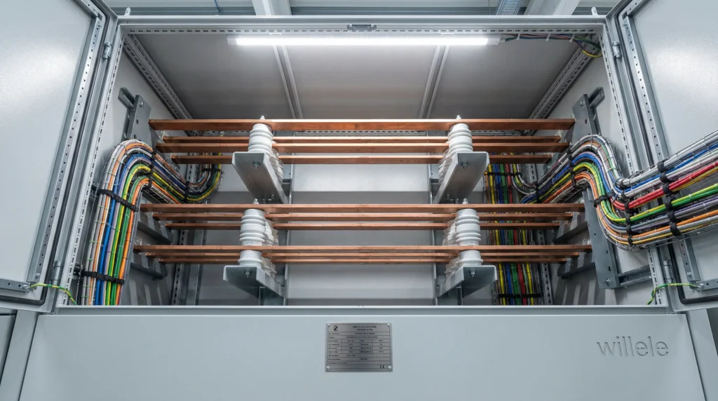
Alt text: Photorealistic industrial installation showing low voltage busbar insulators mounted with copper conductors in electrical cabinet – Willele Electric equipment
Pre-Installation Planning
1. Load Calculation and Busbar Sizing
Before mounting insulators, determine your electrical load requirements:
Current Capacity Formula:
- Busbar cross-sectional area (mm²) = Current (A) ÷ Current density (A/mm²)
- Typical current density: 1.5-2.5 A/mm² for copper
2. Clearance Requirements
| Voltage Level | Minimum Air Gap | Minimum Creepage Distance |
|---|---|---|
| Up to 250V | 3mm | 6mm |
| 251V – 500V | 6mm | 10mm |
| 501V – 750V | 10mm | 16mm |
| 751V – 1000V | 14mm | 20mm |
3. Layout Design
Consider these factors when planning insulator placement:
- Span distance: Maximum 300-400mm between supports for copper busbars
- Phase spacing: Minimum 20mm between phases for low voltage
- Access clearance: 50mm minimum from cabinet walls
- Future expansion: Allow 20% extra space
Step-by-Step Installation Guide
Step 1: Cabinet Preparation
- Power isolation: Ensure complete de-energization and lockout/tagout
- Surface cleaning: Remove paint, rust, or debris from mounting areas
- Marking positions: Use a template or measure precisely
- Verify grounding: Check cabinet grounding integrity
Step 2: Drilling and Mounting Holes
Drilling Guidelines:
| Cabinet Material | Drill Bit Type | Recommended Speed | Lubrication |
|---|---|---|---|
| Steel (mild) | HSS or Cobalt | 500-1000 RPM | Cutting oil |
| Stainless Steel | Cobalt or Carbide | 300-500 RPM | Cutting fluid |
| Aluminum | HSS | 1000-2000 RPM | Kerosene/WD-40 |
| Galvanized Steel | HSS | 500-800 RPM | Cutting oil |
Important Tips:
- Start with a pilot hole (3-4mm)
- Progress to final diameter gradually
- Deburr all holes thoroughly
- Maintain perpendicular drilling angle
Step 3: Installing Insulators
- Position the insulator: Align with pre-drilled holes
- Insert mounting bolts: Use appropriate grade (minimum Grade 8.8)
- Add washers: Use flat and spring washers for vibration resistance
- Hand-tighten nuts: Ensure proper seating before final tightening
- Torque to specification: Follow manufacturer’s torque values
Recommended Torque Values:
| Bolt Size | Torque (Nm) | Torque (ft-lb) |
|---|---|---|
| M5 | 4-5 | 3-4 |
| M6 | 7-9 | 5-7 |
| M8 | 15-18 | 11-13 |
| M10 | 30-35 | 22-26 |
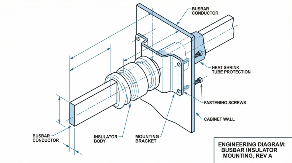
Alt text: Annotated technical schematic diagram showing cutaway view of busbar insulator mounting system with labeled components including bracket, fasteners, and heat shrink tube protection
Step 4: Busbar Installation
- Measure and cut busbars: Allow for thermal expansion (1mm per meter)
- Deburr edges: Smooth all cut edges to prevent corona discharge
- Clean surfaces: Remove oxidation with abrasive cloth
- Position on insulators: Ensure proper alignment across all supports
- Secure with hardware: Use appropriate busbar clamps or bolts
Step 5: Connection and Termination
Connection Best Practices:
- Surface preparation: Clean contact surfaces to bare metal
- Torque connections: Use calibrated torque wrench
- Apply joint compound: Use anti-oxidant compound on aluminum
- Heat shrink protection: Cover exposed connections with appropriate heat shrink tubes
Willele Electric specializes in high-quality heat shrink tubes designed specifically for busbar connections, offering:
- Superior insulation properties
- Excellent mechanical protection
- UV and chemical resistance
- Temperature ratings up to 135°C
Step 6: Phase Identification and Labeling
Apply proper color coding according to local standards:
| Region | Phase L1 | Phase L2 | Phase L3 | Neutral | Ground |
|---|---|---|---|---|---|
| IEC (International) | Brown | Black | Gray | Blue | Green/Yellow |
| US/Canada | Black | Red | Blue | White | Green |
| UK (Old) | Red | Yellow | Blue | Black | Green |
Safety Considerations
Critical Safety Checks:
✓ Verify de-energization with voltage tester
✓ Maintain proper clearances per electrical codes
✓ Use insulated tools when working near live parts
✓ Wear appropriate PPE (gloves, safety glasses, arc-rated clothing)
✓ Follow LOTO procedures strictly
✓ Check insulator integrity for cracks or damage
✓ Verify grounding continuity before energization
✓ Perform insulation resistance testing (minimum 1 MΩ)
Common Installation Mistakes to Avoid:
❌ Over-tightening mounting bolts (can crack insulators)
❌ Insufficient clearance distances
❌ Mixing dissimilar metals without proper treatment
❌ Inadequate support spacing causing busbar sag
❌ Poor surface preparation leading to high contact resistance
❌ Ignoring thermal expansion requirements
❌ Using incorrect hardware grades
Testing and Commissioning
Pre-Energization Tests:
- Visual Inspection
- Check all connections are tight
- Verify proper phase spacing
- Ensure no foreign objects present
- Confirm all hardware is secure
- Insulation Resistance Test
- Test voltage: 500V DC for low voltage systems
- Minimum acceptable: 1 MΩ
- Test between phases and to ground
- Continuity Test
- Verify low resistance across joints
- Typical: <0.1 Ω for properly made connections
- Torque Verification
- Re-check all connection torques
- Document readings for future reference
Initial Energization:
- Energize at reduced voltage if possible
- Monitor for unusual sounds or odors
- Check for excessive heating (thermal imaging recommended)
- Verify voltage balance across phases
Maintenance and Inspection
Regular Maintenance Schedule:
| Inspection Item | Frequency | Action Required |
|---|---|---|
| Visual inspection | Monthly | Check for discoloration, cracks, or damage |
| Thermal scanning | Quarterly | Identify hot spots indicating loose connections |
| Torque verification | Annually | Re-torque all connections to specification |
| Insulation resistance | Annually | Test and document readings |
| Cleaning | Annually | Remove dust and contaminants |
| Hardware inspection | Annually | Replace corroded or damaged components |
Signs of Problems:
- Discoloration or charring around connections
- Visible cracks in insulator material
- Loose or missing hardware
- Excessive heat at connections
- Unusual odors or sounds
- Tracking marks on insulator surfaces
Cost Optimization Tips
- Bulk purchasing: Order insulators and hardware in quantity
- Standardization: Use common sizes across installations
- Quality investment: Premium insulators reduce long-term maintenance
- Proper sizing: Avoid over-specification while maintaining safety margins
- Heat shrink protection: Prevents premature connection failure
Willele Electric offers competitive B2B pricing on bulk orders of busbar insulators and heat shrink tubes, with customization options for specific applications.
Compliance and Standards
Ensure your installation meets relevant standards:
- IEC 61439 – Low-voltage switchgear and controlgear assemblies
- UL 891 – Switchboards (North America)
- IEC 60947 – Low-voltage switchgear and controlgear
- NEMA PB 2 – Deadfront distribution switchboards
- Local electrical codes – Always verify local requirements
Conclusion
Proper mounting of low voltage busbar insulators in electrical cabinets is fundamental to creating safe, reliable, and efficient power distribution systems. By following this comprehensive guide, you can ensure professional-quality installations that meet safety standards and provide years of trouble-free operation.
Remember these key takeaways:
- Plan thoroughly before starting installation
- Use quality components from reputable manufacturers like Willele Electric
- Follow proper torque specifications and clearance requirements
- Protect connections with appropriate heat shrink tubes
- Perform thorough testing before energization
- Maintain regular inspection schedules
For high-quality busbar insulators, heat shrink tubes, and electrical cabinet components, Willele Electric offers comprehensive B2B solutions tailored to your specific requirements.
Frequently Asked Questions (FAQ)
Q1: What is the maximum span between busbar insulators?
A: For copper busbars, the maximum recommended span is 300-400mm depending on busbar thickness and current rating. Heavier loads require closer spacing to prevent sagging and mechanical stress.
Q2: Can I reuse busbar insulators after removal?
A: Only if they show no signs of damage, cracking, tracking, or thermal stress. Always perform visual inspection and insulation resistance testing before reuse. When in doubt, replace with new insulators.
Q3: What’s the difference between DMC and SMC insulators?
A: DMC (Dough Molding Compound) insulators are cost-effective for general applications, while SMC (Sheet Molding Compound) offers superior mechanical strength and better dimensional stability, making them ideal for high-stress installations.
Q4: How do I calculate the correct torque for busbar connections?
A: Torque values depend on bolt size and material. Use manufacturer specifications when available. As a general guide: M6 bolts = 7-9 Nm, M8 = 15-18 Nm, M10 = 30-35 Nm. Always use a calibrated torque wrench.
Q5: Why should I use heat shrink tubes on busbar connections?
A: Heat shrink tubes provide electrical insulation, mechanical protection, moisture sealing, and prevent oxidation of connections. Willele Electric’s specialized heat shrink tubes offer superior protection for long-term reliability.
Q6: What causes tracking on busbar insulators?
A: Tracking occurs due to surface contamination (dust, moisture, conductive particles), excessive voltage stress, or poor-quality insulator material. Regular cleaning and using high-quality insulators prevents this issue.
Q7: How often should I perform thermal imaging on busbar installations?
A: Quarterly thermal imaging is recommended for critical installations. Annual inspection is minimum for standard applications. Always perform thermal scans after initial energization and after any maintenance work.
Q8: Can aluminum and copper busbars be connected directly?
A: Direct connection is not recommended due to galvanic corrosion. Use bi-metallic transition plates or connectors, and apply anti-oxidant compound. Proper heat shrink tube protection is essential for these connections.
