
The Complete Guide to Cable Lug Specifications for Industrial Applications

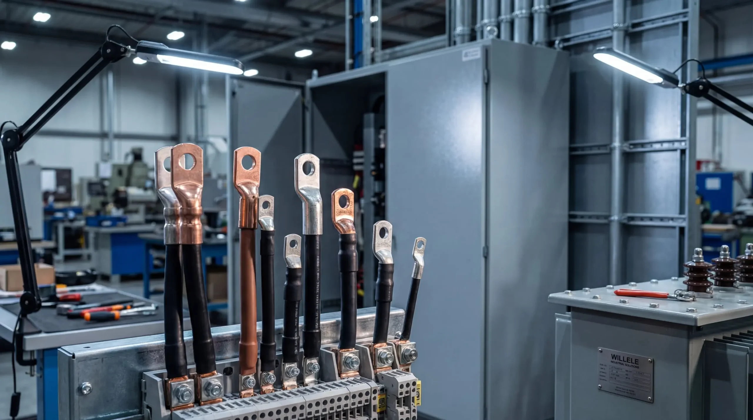
Cable lugs serve as the critical interface between electrical cables and equipment in industrial settings, ensuring safe and efficient power transmission. Understanding proper cable lug specifications is essential for maintaining system reliability, preventing electrical failures, and ensuring workplace safety. This comprehensive guide explores everything you need to know about selecting, installing, and maintaining cable lugs for industrial applications.
Understanding Cable Lug Fundamentals
Cable lugs, also known as cable terminals or cable connectors, are metallic components designed to terminate electrical cables securely to equipment, bus bars, or other electrical devices. These seemingly small components play an outsized role in electrical system performance, as improper selection or installation can lead to increased resistance, overheating, and potential system failures.
The primary function of a cable lug extends beyond simple mechanical connection. These components must provide excellent electrical conductivity, withstand mechanical stress from vibration and thermal cycling, resist environmental degradation, and maintain connection integrity over decades of service life. In industrial environments where power demands are substantial and reliability is non-negotiable, the quality and proper specification of cable lugs directly impacts operational continuity and safety.
Material Selection: Copper, Aluminum, and Bimetallic Options
Material selection represents one of the most critical decisions when specifying cable lugs for industrial applications. Each material offers distinct advantages and limitations that must be carefully evaluated against specific application requirements.
Copper cable lugs remain the gold standard for industrial electrical connections due to their exceptional electrical conductivity, second only to silver. This superior conductivity translates directly into lower electrical resistance, reduced energy losses, and minimal heat generation at connection points. Copper’s mechanical properties also make it ideal for crimping applications, as the material can withstand significant compression forces without cracking while maintaining excellent ductility. The natural corrosion resistance of copper, particularly when tin-plated, makes these lugs suitable for both indoor and outdoor installations. Industrial facilities typically specify copper lugs for high-current applications, critical power distribution systems, and environments where connection reliability cannot be compromised.
Aluminum cable lugs offer compelling advantages in specific applications, particularly where weight reduction and cost considerations are paramount. With approximately 61% of copper’s conductivity, aluminum requires larger cross-sectional areas to carry equivalent current loads, but the material’s significantly lower density results in lighter overall installations. This weight advantage becomes particularly relevant in large-scale power distribution, overhead line applications, and utility installations where cable weight directly impacts support structure requirements. However, aluminum presents unique challenges that must be addressed through proper specification and installation practices. The material forms an insulating oxide layer when exposed to air, which can compromise electrical connections if not properly managed. Modern aluminum lugs incorporate anti-oxide compounds within the barrel that break down this insulating layer during crimping, ensuring reliable electrical contact.
Bimetallic cable lugs represent the engineered solution for connecting dissimilar conductor materials, specifically addressing the galvanic corrosion that occurs when copper and aluminum are directly joined. These specialized lugs feature an aluminum barrel friction-welded to a copper palm, creating a permanent metallurgical bond that eliminates the electrochemical reaction between dissimilar metals. The aluminum barrel accommodates aluminum conductors while the copper palm connects to copper bus bars or equipment terminals. This design prevents the accelerated corrosion and connection degradation that would otherwise occur at the junction of dissimilar metals. Industrial facilities with mixed copper and aluminum infrastructure rely on bimetallic lugs to ensure long-term connection reliability without the need for frequent maintenance or replacement.
Cable Lug Types and Construction Methods
Industrial applications utilize various cable lug designs, each optimized for specific installation methods and performance requirements. Understanding these distinctions enables proper specification for your particular application.
Compression lugs represent the industry standard for heavy-duty industrial applications, utilizing hydraulic or mechanical crimping tools to permanently deform the lug barrel around the cable conductor. This crimping process creates a gas-tight connection that prevents oxidation and maintains low contact resistance over time. The seamless construction of quality compression lugs, manufactured from solid copper or aluminum tubing, ensures uniform wall thickness and eliminates potential weak points. These lugs undergo an annealing process that optimizes the material’s structural characteristics, allowing proper compression without cracking while maintaining excellent conductivity. Compression lugs are specified for applications ranging from low-voltage control circuits to high-voltage power distribution systems up to 33kV.
Mechanical cable lugs offer distinct advantages in applications requiring field serviceability or temporary installations. Rather than permanent crimping, these lugs employ set screws or bolts to clamp the conductor mechanically. This design allows for tool-free or simple wrench-based installation and permits future disassembly for equipment maintenance or system reconfiguration. However, mechanical lugs require careful attention to proper torque specifications during installation, as insufficient tightening leads to high resistance connections while excessive torque can damage conductor strands. These lugs find particular application in control panels, temporary power distribution, and situations where connection accessibility for future maintenance is a priority.
Ring terminal lugs, featuring a circular contact surface with a central hole, represent the most common lug configuration for industrial applications. The closed-ring design prevents accidental disconnection even if the mounting bolt loosens, providing superior mechanical security compared to fork or spade terminals. The flat contact surface ensures maximum contact area with bus bars or equipment terminals, minimizing contact resistance and heat generation. Industrial specifications typically call for ring terminals in applications involving vibration, where connection security is paramount, or where electrical codes mandate enclosed terminal designs.
Critical Specifications and Sizing Parameters
Proper cable lug sizing requires careful consideration of multiple parameters to ensure safe, reliable connections that meet both electrical and mechanical requirements. The following table provides guidance for matching cable sizes to appropriate lug specifications:
| Cable Size (mm²) | Cable Size (AWG/MCM) | Recommended Stud Size | Typical Current Rating | Application Category |
|---|---|---|---|---|
| 1.5 – 4 | 16 – 12 AWG | M4 – M5 | 15 – 25A | Control circuits, instrumentation |
| 6 – 10 | 10 – 8 AWG | M5 – M6 | 30 – 50A | Light industrial, motor controls |
| 16 – 25 | 6 – 4 AWG | M8 – M10 | 60 – 100A | Medium industrial loads |
| 35 – 50 | 2 – 1/0 AWG | M10 – M12 | 125 – 200A | Heavy industrial equipment |
| 70 – 95 | 2/0 – 4/0 AWG | M12 – M16 | 250 – 350A | Main distribution feeders |
| 120 – 185 | 250 – 350 MCM | M16 – M20 | 400 – 600A | Primary power distribution |
| 240 – 400 | 500 – 750 MCM | M20 – M24 | 700 – 1000A | Utility connections, substations |
| 500 – 630 | 1000+ MCM | M24 – M30 | 1200 – 1500A | High-capacity industrial feeders |
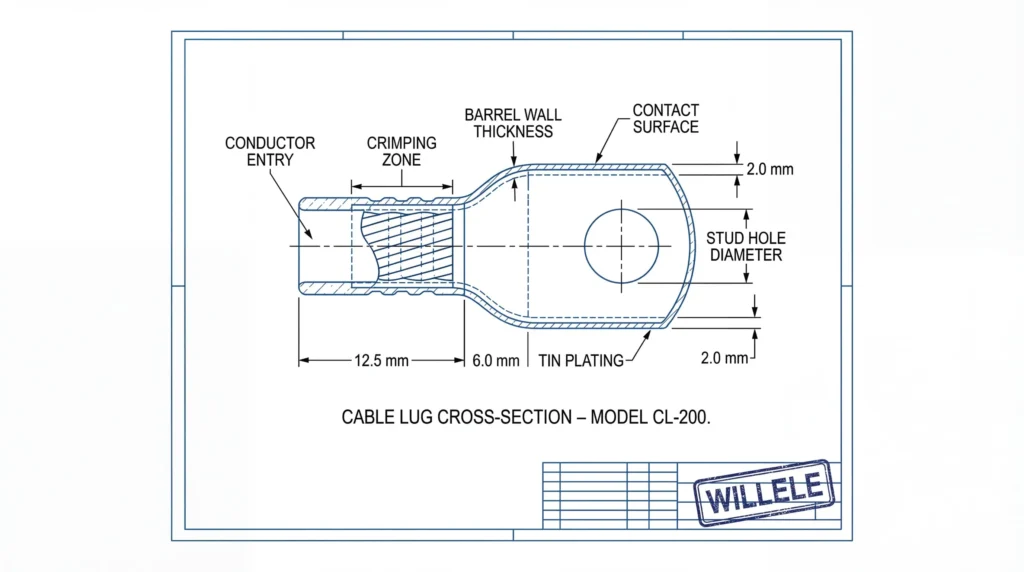
The conductor cross-sectional area represents the primary sizing parameter, determining the lug’s current-carrying capacity and mechanical strength. Manufacturers provide detailed cable lug size charts that correlate conductor sizes with appropriate lug models, but proper selection requires understanding the complete operating context. The barrel internal diameter must accommodate the conductor with sufficient clearance for easy insertion while maintaining adequate wall thickness for structural integrity during crimping. Undersized barrels prevent proper conductor insertion and risk damaging conductor strands, while oversized barrels result in inadequate crimping compression and poor electrical contact.
Stud hole diameter and spacing must match the equipment terminal or bus bar configuration exactly. Standard metric sizes range from M4 for small control applications to M30 for heavy industrial feeders, with each size corresponding to specific bolt diameters and torque requirements. The contact palm thickness and surface area directly influence the connection’s current-carrying capacity and thermal performance. Inadequate contact area creates high-resistance connections that generate excessive heat under load, potentially leading to connection failure or fire hazards.
Barrel length must provide sufficient crimping area to develop the required mechanical strength while accommodating the full conductor cross-section. Industry standards typically specify that the crimped connection should achieve at least 95% of the conductor’s rated tensile strength, ensuring that mechanical failures occur in the cable rather than at the termination. The overall lug dimensions, including length and width, must fit within available installation space while maintaining required electrical clearances to adjacent conductors or grounded surfaces.
International Standards and Compliance Requirements
Industrial cable lug specifications must comply with various international standards that ensure product quality, safety, and performance consistency. Understanding these standards is essential for proper specification and procurement.
The International Electrotechnical Commission (IEC) provides globally recognized standards for cable lugs through IEC 61238-1, which specifies electrical and mechanical properties, testing requirements, and performance criteria. This standard covers aspects including contact resistance limits, temperature rise under rated current, mechanical strength requirements, and short-circuit withstand capability. IEC standards emphasize minimum device safety requirements and establish testing protocols that manufacturers must follow to demonstrate compliance.
Underwriters Laboratories (UL) standards, particularly UL 486A-B for copper connectors and UL 486C for aluminum connectors, provide comprehensive technical details concerning safety and application requirements specific to the North American market. UL certification involves rigorous testing of mechanical strength, electrical conductivity, thermal performance, and long-term reliability under various environmental conditions. Products bearing UL listing marks have undergone independent third-party testing and ongoing factory inspections to verify continued compliance.
The Deutsches Institut für Normung (DIN) standards, widely recognized throughout Europe, cover dimensions, materials, testing methods, and application guidelines through standards such as DIN 46235. These specifications define precise dimensional tolerances, material purity requirements, and crimping tool compatibility, ensuring interchangeability and consistent performance across manufacturers.
The National Electrical Manufacturers Association (NEMA) provides standards specifically addressing North American applications, outlining specifications for cable lugs used in various environmental conditions and ensuring compatibility with standard electrical equipment configurations. NEMA standards consider factors such as ambient temperature ranges, humidity exposure, and chemical resistance requirements common in industrial environments.
Compliance with these standards provides assurance that cable lugs will perform reliably under specified conditions, but proper application still requires careful consideration of site-specific factors including ambient temperature, altitude, pollution levels, and exposure to corrosive substances or mechanical stress.
Installation Best Practices and Crimping Specifications
Proper installation technique is equally important as correct specification in achieving reliable cable lug connections. Even the highest-quality components will fail if installation procedures are inadequate.
Cable preparation begins with removing the appropriate length of insulation to expose the conductor, typically matching the lug barrel depth plus a small allowance. The exposed conductor must be thoroughly cleaned to remove any oxidation, dirt, or contamination that could compromise electrical contact. For aluminum conductors, applying anti-oxide compound to the exposed strands is essential to prevent oxide layer formation that would otherwise create high-resistance connections. The conductor strands should be inspected for damage, with any broken or frayed strands indicating the need for re-stripping or cable replacement.
Crimping tool selection and die matching represent critical factors in achieving proper compression. Each lug size requires a specific crimping die that produces the correct compression ratio, typically reducing the barrel diameter by 15-25% depending on the lug design and conductor type. Using incorrect dies, even if they appear to fit, results in either under-crimping that leaves gaps and high resistance, or over-crimping that damages conductor strands and reduces mechanical strength. Hydraulic crimping tools provide consistent, controlled compression force and are mandatory for larger cable sizes where manual tools cannot generate adequate force.
The crimping process itself requires attention to proper conductor insertion depth, ensuring strands reach the barrel’s end without protruding beyond it. The crimp should be centered on the barrel, avoiding the transition zone between barrel and palm where stress concentrations occur. After crimping, visual inspection should confirm uniform compression around the barrel circumference, with no cracks, splits, or incomplete die closure. The crimped connection should be mechanically tested by attempting to pull the conductor from the lug, verifying that the connection strength meets or exceeds specifications.
Material Comparison: Performance and Application Considerations
Selecting between copper and aluminum cable lugs requires evaluating multiple performance factors against specific application requirements and constraints. The following comparison table highlights key differences:
| Performance Factor | Copper Cable Lugs | Aluminum Cable Lugs | Bimetallic Cable Lugs |
|---|---|---|---|
| Electrical Conductivity | Excellent (100% IACS) | Good (61% IACS) | Excellent (optimized transition) |
| Weight (relative) | Heavy (baseline) | Light (70% lighter) | Medium (hybrid) |
| Corrosion Resistance | Excellent (especially tin-plated) | Moderate (requires oxide inhibitor) | Excellent (protected junction) |
| Cost (relative) | Higher initial cost | Lower initial cost | Highest initial cost |
| Mechanical Strength | Superior ductility and tensile strength | Lower tensile strength | Optimized for both materials |
| Thermal Performance | Excellent heat dissipation | Good (requires larger sizes) | Excellent (copper palm contact) |
| Installation Complexity | Standard crimping procedures | Requires oxide compound and specific techniques | Standard crimping with material-specific dies |
| Long-term Reliability | Excellent with minimal maintenance | Good with proper installation | Excellent for dissimilar metal connections |
| Vibration Resistance | Excellent | Good (requires proper sizing) | Excellent |
| Best Applications | High-current, critical systems, compact installations | Large-scale distribution, weight-sensitive applications | Copper-to-aluminum transitions |
This comparison demonstrates that material selection should be driven by specific application requirements rather than cost considerations alone. While aluminum lugs offer initial cost savings, the need for larger sizes to achieve equivalent current capacity and more stringent installation requirements may offset these savings in certain applications. Copper lugs justify their higher cost through superior performance in high-current, space-constrained, or vibration-prone installations where connection reliability is paramount.
Environmental Considerations and Protection Methods
Industrial environments expose cable lugs to various degradation mechanisms that must be addressed through proper specification and protection methods. Understanding these environmental factors ensures long-term connection reliability.
Temperature extremes affect both the electrical and mechanical properties of cable lugs. High ambient temperatures reduce current-carrying capacity and accelerate oxidation processes, while thermal cycling from load variations creates expansion and contraction that can loosen mechanical connections over time. Tin plating on copper lugs provides enhanced oxidation resistance at elevated temperatures, maintaining low contact resistance even after years of thermal cycling. For applications exceeding standard temperature ratings, specialized high-temperature lugs with enhanced annealing and plating processes are available.
Moisture and humidity exposure accelerates corrosion, particularly in aluminum lugs where the oxide layer can trap moisture and create high-resistance connections. Sealed or insulated lugs with integrated protective sleeves prevent moisture ingress at the cable-to-lug interface, while proper application of heat-shrink tubing or insulating boots protects the entire termination. Marine and coastal installations require additional protection through tin-plated or nickel-plated lugs that resist salt spray corrosion.
Chemical exposure in industrial facilities can rapidly degrade cable lugs if materials are not properly selected. Acids, alkalis, solvents, and industrial chemicals attack both the lug material and any protective plating, leading to accelerated corrosion and connection failure. Stainless steel lugs or specially coated copper lugs provide enhanced chemical resistance for these demanding applications, though careful verification of compatibility with specific chemicals is essential.
Mechanical stress from vibration, movement, or physical impact requires robust lug designs with adequate mechanical strength and secure mounting. Compression lugs generally provide superior vibration resistance compared to mechanical lugs, as the crimped connection cannot loosen over time. Applications involving significant vibration should specify lugs with reinforced barrel designs and utilize proper cable strain relief to prevent stress concentration at the termination point.
Quality Verification and Testing Protocols
Ensuring cable lug quality requires comprehensive testing protocols that verify both manufacturing quality and installation integrity. Industrial facilities should implement systematic verification procedures to prevent connection failures.
Visual inspection represents the first line of quality verification, examining lugs for surface defects, cracks, burrs, or inconsistent plating that indicate manufacturing defects. The barrel interior should be smooth and free from obstructions, while the contact surface should be flat and perpendicular to the barrel axis. Dimensional verification using calipers or specialized gauges confirms that critical dimensions including stud hole diameter, barrel internal diameter, and overall length meet specifications.
Electrical testing of installed terminations verifies connection quality through resistance measurement. A properly crimped connection should exhibit resistance essentially equal to an equivalent length of conductor, typically less than 10 microhms for medium-sized lugs. Elevated resistance indicates inadequate crimping, contamination, or material defects requiring correction before energization. Thermographic inspection after energization identifies high-resistance connections through elevated temperature, allowing corrective action before connection failure occurs.
Mechanical pull testing verifies that crimped connections achieve required tensile strength, typically 95% of the conductor’s rated strength. While destructive testing cannot be performed on every connection, periodic sampling during large installations provides confidence in installation quality and crimping tool performance. Non-destructive mechanical testing through controlled pulling force can verify connection integrity without damaging the termination.
Documentation of cable lug specifications, installation procedures, and test results provides essential records for maintenance planning and troubleshooting. Recording lug manufacturer, model number, installation date, crimping tool and die specifications, and test results enables future maintenance personnel to understand the installation and make informed decisions regarding inspection intervals or replacement requirements.
Frequently Asked Questions
What is the difference between compression and mechanical cable lugs?
Compression lugs are permanently crimped onto the conductor using hydraulic or mechanical tools, creating a gas-tight connection that cannot be disassembled. Mechanical lugs use set screws or bolts to clamp the conductor, allowing for future removal and reinstallation. Compression lugs provide superior long-term reliability and are preferred for permanent installations, while mechanical lugs offer advantages in applications requiring serviceability or temporary connections.
Can I use copper cable lugs with aluminum conductors?
No, copper lugs should only be used with copper conductors. Connecting aluminum conductors to copper lugs creates galvanic corrosion that rapidly degrades the connection. For aluminum conductors, use aluminum cable lugs or bimetallic lugs specifically designed for aluminum-to-copper transitions.
How do I determine the correct crimping die for my cable lug?
The crimping die must match both the lug size and the crimping tool manufacturer’s specifications. Most manufacturers color-code their lugs to indicate the required die size, with standardized colors across the industry. Always consult the lug manufacturer’s technical documentation and the crimping tool’s die selection chart to ensure proper matching. Using incorrect dies, even if they appear to fit, will result in unreliable connections.
What causes cable lug connections to overheat?
Overheating typically results from high electrical resistance at the connection point, caused by inadequate crimping compression, contamination or oxidation at the contact surfaces, undersized lugs for the current load, or loose mechanical connections. Proper lug sizing, thorough cleaning before installation, correct crimping procedures, and periodic thermographic inspection prevent overheating issues.
How often should cable lug connections be inspected in industrial facilities?
Inspection frequency depends on the operating environment and criticality of the circuit. Critical power distribution connections should undergo thermographic inspection annually, while less critical circuits may be inspected every three to five years. Facilities with high vibration, temperature extremes, or corrosive environments require more frequent inspection. Any connection showing signs of overheating, discoloration, or corrosion should be immediately investigated and corrected.
Willele Electric specializes in high-quality heat shrink tubing and electrical connection solutions for industrial applications. Our products meet international standards and provide reliable protection for cable terminations in demanding environments. For technical support or product specifications, visit willele.com.
