
Cable Lugs for Solar Panel Installation: Complete Connection Guide

Solar photovoltaic systems demand reliable electrical connections that can withstand decades of outdoor exposure while maintaining optimal conductivity. Cable lugs serve as the critical junction points in these installations, connecting solar panels to inverters, charge controllers, and battery banks. Understanding proper lug selection, installation techniques, and industry standards ensures system safety, efficiency, and longevity. This comprehensive guide addresses the technical requirements and best practices for cable lug implementation in solar panel installations.
Understanding Cable Lugs in Solar Applications
Cable lugs, also known as cable terminals or ring terminals, are electrical connectors that terminate cables to equipment terminals, bus bars, and grounding systems. In solar installations, these components handle direct current loads ranging from residential systems producing several kilowatts to commercial arrays generating hundreds of kilowatts. The harsh environmental conditions—including UV radiation, temperature extremes from -40°C to +90°C, moisture exposure, and mechanical vibration—demand specialized lugs engineered for photovoltaic applications.
The fundamental purpose of cable lugs in solar systems extends beyond simple mechanical connection. These components must maintain low contact resistance throughout the system’s operational lifetime, typically 25 years or more. According to IEC 61238-1 standards, properly installed lugs should exhibit a maximum resistance increase of only 1.5 times compared to the reference conductor, preventing energy losses and dangerous hot spots that could compromise system performance or create fire hazards.
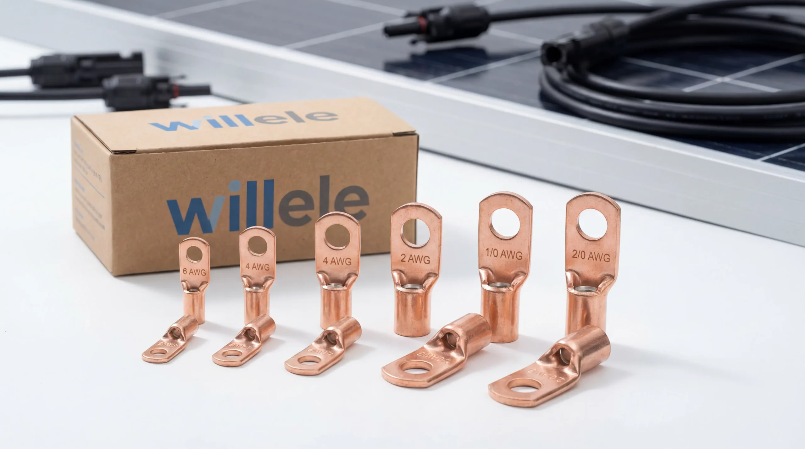
Professional-grade cable lugs designed for solar panel installations, featuring tinned copper construction and inspection holes for quality verification
Types of Cable Lugs for Solar Installations
Solar installations utilize several distinct lug configurations, each optimized for specific connection requirements within the photovoltaic system architecture.
Ring Terminal Lugs
Ring terminal lugs represent the most common configuration for solar applications, featuring a circular opening that slides over equipment studs or bolts. This closed-loop design prevents accidental disconnection during installation or maintenance activities. Ring lugs connect solar cables to inverter terminals, combiner box bus bars, charge controller inputs, and battery bank terminals. The complete circular design ensures consistent contact pressure around the entire stud circumference, distributing electrical load evenly and minimizing resistance.
Pin Lugs (Tube Lugs)
Pin lugs, characterized by their cylindrical barrel design, insert directly into equipment terminals without requiring stud hardware. These lugs find application in specific inverter models and control equipment where manufacturers specify pin-type terminations. The streamlined profile reduces connection bulk in densely packed electrical enclosures, though they require compatible receiving terminals with set-screw or spring-clamp retention mechanisms.
Grounding Lugs
Grounding lugs serve the critical safety function of bonding solar array frames, mounting structures, and equipment enclosures to the system grounding conductor. Solar-specific grounding lugs often feature lay-in designs that accommodate continuous grounding conductors without cutting, enabling efficient daisy-chain connections across multiple panels or mounting rails. These specialized lugs incorporate corrosion-resistant materials and weather-sealed designs to maintain reliable ground paths throughout decades of outdoor exposure.
Material Selection and Construction Standards
The material composition of cable lugs directly impacts their electrical performance, corrosion resistance, and mechanical durability in solar installations.
Copper vs. Aluminum Construction
High-purity copper dominates solar cable lug manufacturing due to its superior electrical conductivity—approximately 61% higher than aluminum. Copper’s excellent conductivity translates to lower voltage drops and reduced resistive heating at connection points, critical factors in maximizing solar system efficiency. Copper also exhibits superior mechanical properties, withstanding repeated thermal cycling and vibration without work-hardening or connection degradation.
Aluminum lugs offer cost advantages for large-scale installations but require larger cross-sectional areas to match copper’s current-carrying capacity. When aluminum lugs connect to copper bus bars or terminals, installers must employ anti-oxidant compounds and follow specific torque specifications to prevent galvanic corrosion at dissimilar metal interfaces.
Tinned Copper Advantages
Tinned copper lugs feature a thin tin plating over the copper base material, providing enhanced corrosion protection in marine, coastal, and high-humidity environments. The tin coating prevents copper oxidation, which can increase contact resistance over time. For solar installations in corrosive atmospheres, tinned copper lugs represent the optimal balance of conductivity, durability, and long-term reliability. The tin plating also improves solderability for applications requiring additional connection methods beyond mechanical crimping.
Cable Lug Sizing and Selection Criteria
Proper lug sizing ensures safe current handling, mechanical integrity, and compliance with electrical codes governing solar installations.
Wire Gauge Compatibility
Cable lugs must precisely match the conductor size they terminate. Solar installations commonly employ wire gauges ranging from 14 AWG for small residential systems to 2/0 AWG or larger for commercial arrays. The lug barrel diameter must accommodate all conductor strands without excessive compression or loose fit. Undersized lugs cannot fully contain the conductor, creating high-resistance connections prone to overheating. Oversized lugs fail to achieve proper crimp compression, resulting in loose connections that may separate under mechanical stress or thermal cycling.
| Wire Size (AWG) | Typical Application | Maximum Current (30°C) | Recommended Lug Stud Size |
|---|---|---|---|
| 14 AWG | Small panels, control circuits | 25A | 1/4″ (M6) |
| 12 AWG | Residential panel strings | 30A | 1/4″ (M6) |
| 10 AWG | Residential arrays, charge controllers | 40A | 5/16″ (M8) |
| 8 AWG | Medium residential systems | 55A | 5/16″ (M8) |
| 6 AWG | Large residential, small commercial | 75A | 3/8″ (M10) |
| 4 AWG | Commercial arrays, battery banks | 95A | 3/8″ (M10) |
| 2 AWG | Large commercial systems | 130A | 1/2″ (M12) |
| 1/0 AWG | High-power inverter connections | 170A | 1/2″ (M12) |
| 2/0 AWG | Main DC conductors, large battery banks | 195A | 5/8″ (M16) |
Stud Hole Sizing
The lug’s stud hole diameter must match the equipment terminal bolt size, ensuring proper mechanical contact and preventing connection looseness. Common solar equipment utilizes metric (M6, M8, M10, M12) or imperial (1/4″, 5/16″, 3/8″, 1/2″) stud sizes. Installers should verify equipment specifications before purchasing lugs, as mismatched stud holes compromise connection integrity and may violate electrical code requirements.
Voltage Rating Considerations
Solar cable lugs must carry voltage ratings appropriate for system design voltage. Residential systems typically operate at 300-600V DC, while commercial installations may reach 1000V DC or higher. UL-listed lugs rated for 600V AC applications generally prove suitable for 1000V DC solar systems, as the uninsulated lug itself presents minimal voltage-dependent failure mechanisms. However, the complete connection assembly—including heat shrink insulation and terminal spacing—must meet voltage-specific clearance requirements defined in NEC Article 690 and IEC 62852 standards.
Crimping Tools and Techniques
Proper crimping represents the single most critical factor in creating reliable cable lug connections for solar installations. Poor crimping techniques account for the majority of connection failures, leading to increased resistance, overheating, and potential fire hazards.
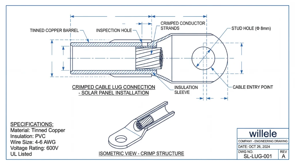
Technical cross-section showing proper crimp compression and conductor insertion depth in a cable lug assembly
Hydraulic vs. Manual Crimping Tools
Hydraulic crimping tools deliver consistent, high-pressure compression required for large-gauge conductors (4 AWG and larger). These tools employ calibrated dies that produce hexagonal or indent-style crimps meeting manufacturer specifications. The hydraulic mechanism ensures complete crimp compression regardless of operator strength, critical for achieving the cold-welding effect that creates gas-tight connections between lug barrel and conductor strands.
Manual ratcheting crimpers serve adequately for smaller conductors (10 AWG to 6 AWG) in residential installations. Quality manual tools incorporate ratchet mechanisms that prevent premature release, ensuring full crimp cycle completion. However, generic pliers or adjustable crimpers cannot deliver the precise compression profiles required for reliable solar connections and should never be used in professional installations.
Die Selection and Crimp Profiles
Crimping dies must match both the lug manufacturer and conductor size. Hexagonal dies create six-point compression patterns that distribute force evenly around the lug barrel, while indent dies produce localized compression points. The die selection directly affects the crimp’s mechanical strength and electrical resistance. Using incorrect dies—even if they appear to fit—can result in under-crimped connections that fail prematurely or over-crimped connections that damage conductor strands and reduce current-carrying capacity.
Step-by-Step Crimping Process
Achieving professional-quality crimps requires systematic attention to each installation step. Begin by selecting the correct lug for both conductor size and stud diameter. Strip the cable insulation to expose conductor length matching the lug barrel depth, typically 10-15mm for most solar applications. Avoid nicking or cutting individual conductor strands during stripping, as damaged strands reduce the effective conductor cross-section and create stress concentration points.
Insert the stripped conductor fully into the lug barrel until it reaches the barrel end. Many quality lugs incorporate inspection holes that allow visual verification of proper conductor insertion depth. Position the crimping die on the lug barrel according to manufacturer specifications—typically centered on the barrel for single-compression lugs or at specified intervals for multi-compression designs. Apply steady pressure until the crimping tool completes its full cycle, indicated by the ratchet release in manual tools or pressure relief in hydraulic tools.
Inspect the completed crimp for proper compression depth and symmetry. The crimped barrel should show uniform compression around its circumference without excessive deformation or “wings” that indicate over-crimping. Perform a pull test by firmly tugging the cable—a properly crimped lug should show no movement or separation from the conductor. For critical connections, measure the crimp dimensions with calipers and compare against manufacturer specifications to verify compliance.
Installation Best Practices for Solar Systems
Beyond proper crimping, several installation practices ensure long-term connection reliability in solar photovoltaic systems.
Torque Specifications and Hardware
Equipment terminals require specific torque values to achieve optimal contact pressure without damaging threads or deforming lugs. Under-torqued connections exhibit high resistance and may loosen over time due to thermal cycling. Over-torqued connections can strip threads, crack lugs, or deform bus bars, creating unreliable contact surfaces. Solar installers should reference equipment manufacturer specifications and employ calibrated torque wrenches for all lug connections.
| Terminal Stud Size | Recommended Torque | Typical Application |
|---|---|---|
| M6 (1/4″) | 5-7 N⋅m (44-62 lb⋅in) | Small panels, control circuits |
| M8 (5/16″) | 10-12 N⋅m (88-106 lb⋅in) | Charge controllers, small inverters |
| M10 (3/8″) | 15-20 N⋅m (133-177 lb⋅in) | Residential inverters, combiner boxes |
| M12 (1/2″) | 25-30 N⋅m (221-265 lb⋅in) | Commercial inverters, battery terminals |
| M16 (5/8″) | 40-50 N⋅m (354-442 lb⋅in) | Large battery banks, main DC disconnects |
Heat Shrink Insulation Application
Exposed lug connections require insulation to prevent accidental contact, short circuits, and corrosion. Adhesive-lined heat shrink tubing provides superior environmental protection compared to standard heat shrink or electrical tape. The adhesive inner layer creates a moisture seal that prevents water ingress and corrosion at the crimp interface. Select heat shrink with 3:1 or 4:1 shrink ratios to accommodate the diameter transition from cable to lug, and choose products rated for the system’s operating temperature range and voltage class.
Apply heat shrink before crimping the lug, sliding it onto the cable beyond the crimp location. After completing and inspecting the crimp, position the heat shrink to cover the entire barrel and extend onto the cable insulation by at least 25mm. Apply heat evenly using a heat gun, working from the center outward to eliminate air pockets. The adhesive should visibly flow from both ends of the heat shrink, indicating complete sealing.
Polarity Management and Color Coding
Solar installations must maintain consistent polarity throughout the DC system to prevent reverse current flow and equipment damage. Industry convention designates red cables and lugs for positive conductors and black for negative conductors, with green or bare copper reserved exclusively for grounding. Maintaining this color coding from panels through combiner boxes, charge controllers, and inverters simplifies troubleshooting and reduces installation errors. For systems requiring additional circuit identification, use colored heat shrink or cable labels at each connection point.
Compliance with International Standards
Solar cable lug installations must conform to multiple international and regional standards governing electrical safety, product certification, and installation practices.
IEC Standards for Cable Lugs
IEC 61238-1 establishes performance requirements for cable lugs and connectors, specifying mechanical strength, contact resistance, temperature rise limits, and environmental durability. Lugs meeting this standard undergo rigorous testing including current cycling, thermal shock, vibration resistance, and corrosion exposure. For solar applications, IEC 62852 defines additional requirements for DC connectors and terminations, addressing the unique challenges of photovoltaic systems including arc fault prevention and UV resistance.
UL Certification Requirements
In North American markets, UL 486A-B certification indicates cable lugs meet safety standards for electrical connections. UL-listed lugs undergo testing for temperature rise, current-carrying capacity, and mechanical strength. The certification specifies maximum voltage ratings, with many solar-grade lugs certified for 600V AC or 1000V DC applications. Installers should verify that all lugs carry appropriate UL markings and that installation methods comply with UL specifications to maintain system certification and warranty coverage.
National Electrical Code (NEC) Compliance
NEC Article 690 governs photovoltaic system installations in the United States, establishing requirements for conductor sizing, overcurrent protection, grounding, and connection methods. Section 690.31 specifically addresses PV system connections, requiring that all terminals and splices be accessible for inspection and maintenance. Cable lugs must be installed in approved enclosures or junction boxes that provide environmental protection and prevent accidental contact with live conductors. Grounding connections must follow NEC Article 250 requirements, ensuring low-impedance paths for fault currents.
Common Installation Mistakes and Prevention
Understanding frequent errors in cable lug installation enables proactive prevention and quality assurance in solar projects.
Under-Crimping and Over-Crimping
Under-crimped connections fail to achieve sufficient compression between lug barrel and conductor strands, resulting in high resistance and loose mechanical bonds. These connections exhibit increased temperature rise during operation and may separate completely under vibration or thermal stress. Over-crimped connections damage conductor strands through excessive compression, reducing the effective conductor cross-section and creating stress concentration points where strands may fracture. Both conditions compromise system safety and reliability.
Prevention requires using properly calibrated crimping tools with manufacturer-specified dies. Hydraulic tools should undergo periodic calibration to verify pressure delivery. Installers should inspect each crimp for proper compression depth and perform pull tests to confirm mechanical integrity. For critical installations, consider using crimp force monitoring tools that provide real-time feedback on compression pressure.
Inadequate Conductor Insertion
Partially inserted conductors leave portions of the lug barrel empty, reducing the effective contact area and increasing connection resistance. This condition often goes undetected during visual inspection but manifests as hot spots during system operation. Lugs with inspection holes enable visual verification of full conductor insertion before crimping. For lugs without inspection holes, measure the stripped conductor length against the barrel depth before insertion, and mark the cable insulation to indicate proper insertion depth.
Mixing Incompatible Materials
Connecting copper lugs directly to aluminum bus bars or vice versa creates galvanic corrosion cells that progressively degrade connection quality. The dissimilar metals exhibit different electrochemical potentials, causing accelerated corrosion when moisture provides an electrolyte path. This issue particularly affects outdoor installations and coastal environments where humidity and salt exposure accelerate corrosion.
Prevention requires using transition washers or bi-metallic lugs specifically designed for copper-to-aluminum connections. Apply anti-oxidant compound to aluminum surfaces before assembly, and follow manufacturer torque specifications precisely. Alternatively, specify equipment with bus bars matching the lug material to eliminate dissimilar metal interfaces entirely.
Maintenance and Inspection Protocols
Regular inspection and maintenance of cable lug connections ensures continued system reliability and identifies potential failures before they cause downtime or safety hazards.
Thermal Imaging Surveys
Infrared thermal imaging reveals connection problems invisible to visual inspection. Hot spots indicating elevated resistance appear as temperature anomalies compared to surrounding connections. Annual thermal surveys should be conducted under load conditions when the system operates near peak current output. Temperature differences exceeding 10°C between similar connections warrant investigation and potential re-termination.
Torque Verification Schedule
Connection hardware can loosen over time due to thermal cycling, vibration, and mechanical stress. Establish a torque verification schedule based on system size and environmental conditions. Residential systems in stable environments may require verification only every 3-5 years, while commercial installations in harsh conditions benefit from annual inspection. Use calibrated torque wrenches to verify that all lug connections maintain specified torque values, and re-torque any connections showing looseness.
Corrosion Assessment
Outdoor connections face continuous exposure to moisture, temperature extremes, and atmospheric contaminants that promote corrosion. Inspect all accessible lug connections annually for signs of corrosion including discoloration, surface oxidation, or white/green deposits indicating active corrosion. Connections showing corrosion should be disassembled, cleaned with appropriate contact cleaner, and reassembled with fresh anti-oxidant compound. Severe corrosion requires complete lug replacement to restore connection integrity.
Cable Lug Comparison: Key Selection Factors
| Feature | Copper Lugs | Tinned Copper Lugs | Aluminum Lugs |
|---|---|---|---|
| Electrical Conductivity | Excellent (100% IACS) | Excellent (98% IACS) | Good (61% IACS) |
| Corrosion Resistance | Moderate | Excellent | Moderate (requires compound) |
| Cost | Moderate | Higher | Lower |
| Weight | Moderate | Moderate | Light |
| Mechanical Strength | Excellent | Excellent | Good |
| Best Applications | Indoor, controlled environments | Outdoor, marine, coastal | Large-scale, cost-sensitive |
| Lifespan | 25+ years | 30+ years | 20+ years (with maintenance) |
| Temperature Rating | -40°C to +90°C | -40°C to +90°C | -40°C to +90°C |
Frequently Asked Questions
What size cable lug do I need for my solar panel installation?
Cable lug sizing depends on your conductor gauge and equipment terminal stud size. For residential systems, 10 AWG conductors typically require lugs with 5/16″ (M8) stud holes, while 6 AWG conductors need 3/8″ (M10) stud holes. Always verify your specific equipment terminal specifications and match both the lug barrel to your wire gauge and the stud hole to your terminal bolt size.
Can I use regular electrical lugs for solar panel connections?
Standard electrical lugs can be used for solar installations if they meet voltage ratings (typically 600V minimum) and are UL-listed for the application. However, solar-specific lugs often feature enhanced UV resistance, wider temperature ratings (-40°C to +90°C), and tinned copper construction for superior outdoor durability. For connections exposed to weather, solar-grade lugs provide better long-term reliability.
How tight should I torque cable lug connections?
Torque specifications vary by stud size and equipment manufacturer. Typical ranges are 5-7 N⋅m for M6 studs, 10-12 N⋅m for M8, 15-20 N⋅m for M10, and 25-30 N⋅m for M12. Always consult your equipment manual for exact specifications and use a calibrated torque wrench. Under-torquing creates high-resistance connections, while over-torquing can damage threads or crack lugs.
Do I need special tools to crimp cable lugs for solar installations?
Yes, proper crimping requires matched crimping tools and dies for your lug type and conductor size. Hydraulic crimpers are essential for large conductors (4 AWG and larger), while quality ratcheting crimpers work for smaller sizes. Never use standard pliers or adjustable tools, as they cannot deliver the precise compression required for reliable connections. Investment in proper crimping tools prevents connection failures and ensures system safety.
How often should I inspect cable lug connections in my solar system?
Perform initial inspection within the first year of operation, then establish a schedule based on environmental conditions. Residential systems in moderate climates typically require inspection every 3-5 years, while commercial installations or systems in harsh environments benefit from annual inspection. Use thermal imaging to detect connection problems before they cause failures, and verify torque on all accessible connections during each inspection.
Conclusion
Cable lugs represent critical components in solar photovoltaic installations, directly impacting system safety, efficiency, and longevity. Proper selection requires careful consideration of conductor size, material composition, environmental conditions, and equipment compatibility. Installation quality depends on using appropriate crimping tools, following manufacturer specifications, and adhering to international standards including IEC 61238-1 and NEC Article 690.
The investment in high-quality cable lugs and professional installation techniques pays dividends throughout the system’s operational lifetime. Properly installed connections maintain low resistance, withstand environmental stresses, and require minimal maintenance over decades of service. By following the guidelines and best practices outlined in this guide, solar installers and system owners can ensure reliable electrical connections that maximize energy production while maintaining the highest safety standards.
For B2B partners seeking reliable cable termination solutions for solar installations, willele Electric offers comprehensive product lines engineered for photovoltaic applications. Our heat shrink tubing products provide superior environmental protection for cable lug connections, ensuring long-term reliability in demanding outdoor conditions. Contact our technical team for application-specific recommendations and product specifications tailored to your solar project requirements.
