Marina Electrical System Upgrade Using Waterproof Wire Nuts
Marine electrical environments represent some of the most demanding conditions any electrical component can face. Salt air, constant moisture, vibration from wave action, and temperature extremes combine to create a corrosive gauntlet that destroys standard electrical connections within months. For marina operators, boat yard managers, and marine electrical contractors undertaking a marina electrical system upgrade using waterproof wire nuts, selecting the right components is not merely a performance decision — it is a safety imperative.
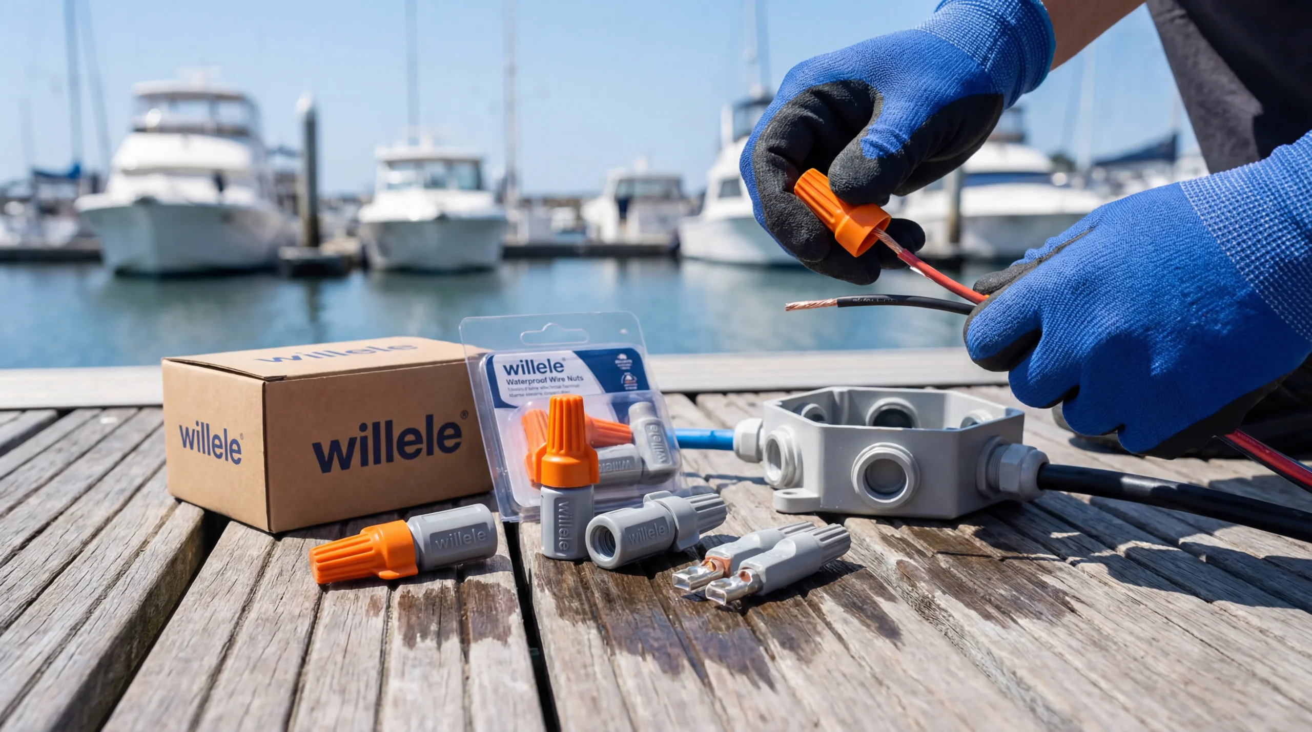
At Willele Electric, we engineer heat shrink tubes and waterproof wire connectors purpose-built for the rigors of marine and marina environments. This guide provides a complete technical and practical framework for planning and executing a marina electrical system upgrade that meets ABYC, NEC Article 553, and NFPA 303 standards.
Why Standard Wire Nuts Fail in Marina Environments
Conventional twist-on wire nuts are engineered for dry, indoor applications. In marina settings, they fail through three primary mechanisms:
Galvanic Corrosion — Salt-laden air accelerates oxidation at bare copper conductor surfaces inside standard wire nuts, increasing resistance and generating heat that can ignite surrounding materials.
Moisture Infiltration — Even brief exposure to rain, spray, or condensation allows water to wick into the connection through capillary action, displacing air and initiating corrosion.
Vibration Loosening — Dock movement, wave action, and vessel engine vibration gradually back out the spring coil inside standard connectors, creating intermittent connections and arc flash hazards.
Waterproof wire nuts — particularly those incorporating silicone gel fill and heat shrink outer sleeves — address all three failure modes simultaneously, making them the only code-compliant choice for below-deck, dock pedestal, and shore power applications.
Marina Electrical System Zones and Requirements
Understanding the distinct electrical zones within a marina guides proper component selection:
| Zone | Location | Exposure Level | Minimum IP Rating | Recommended Connector Type |
|---|---|---|---|---|
| Zone A | Shore power pedestals | Direct weather | IP67 | Gel-filled waterproof wire nut + heat shrink |
| Zone B | Dock wiring runs | Splash/rain | IP65 | Gel-filled waterproof wire nut |
| Zone C | Below-deck boat connections | Immersion risk | IP68 | Marine-grade heat shrink butt connector |
| Zone D | Dry marina office/building | Indoor dry | IP30 | Standard listed wire nut acceptable |
| Zone E | Fuel dock area | Hazardous (Class I, Div 2) | Explosion-proof | Listed explosion-proof fittings only |
| Zone F | Underwater lighting | Continuous submersion | IP68/IP69K | Fully encapsulated marine connector |
Waterproof Wire Nut Construction: What Makes Them Marine-Grade
Not all products marketed as “waterproof” deliver equivalent protection. Understanding internal construction helps procurement teams and contractors specify correctly.
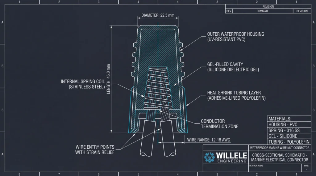
Alt text: Technical engineering cross-section schematic of a Willele waterproof wire nut showing internal components including spring coil, silicone gel cavity, heat shrink tubing layer, and labeled conductor termination zones
Internal Component Breakdown
| Component | Material | Function |
|---|---|---|
| Outer shell | UV-stabilized polypropylene | Physical protection, UV resistance |
| Internal spring coil | Stainless steel 304 | Conductor gripping, vibration resistance |
| Gel fill cavity | Silicone or polyurethane gel | Moisture exclusion, corrosion prevention |
| Heat shrink sleeve | Dual-wall polyolefin with adhesive | Environmental seal, strain relief |
| Wire entry seal | Elastomeric grommet | Cable diameter accommodation |
The dual-wall heat shrink sleeve is the defining feature of premium marine-grade wire nuts. When heated, the outer polyolefin layer shrinks to grip the cable jacket while the inner adhesive layer melts and flows into voids, creating a hermetic seal that withstands salt spray, fuel vapors, and UV degradation.
Waterproof Wire Nut Comparison: Marine Applications
| Specification | Basic Waterproof | Gel-Filled Marine | Dual-Wall Heat Shrink | Willele Premium Marine |
|---|---|---|---|---|
| IP Rating | IP44 | IP65 | IP67 | IP68 |
| Salt Spray Hours | 48 hrs | 200 hrs | 500 hrs | 1,000+ hrs |
| Operating Temp | -10°C to 60°C | -20°C to 70°C | -40°C to 85°C | -55°C to 105°C |
| Wire Range | 22–12 AWG | 22–10 AWG | 22–8 AWG | 22–6 AWG |
| Vibration Rating | Standard | Enhanced | Heavy-duty | Marine certified |
| UV Resistance | None | Basic | Good | Excellent |
| ABYC Compliance | No | Partial | Yes | Full |
| Dielectric Strength | 600V | 600V | 1,000V | 1,000V |
| Installation Method | Twist only | Twist + gel | Twist + heat | Twist + heat + gel |
| Typical Lifespan (marine) | 1–2 years | 3–5 years | 7–10 years | 15+ years |
Step-by-Step Marina Electrical Upgrade Process
Phase 1: Assessment and Planning
Begin every marina electrical system upgrade with a comprehensive load audit. Document all shore power pedestals, lighting circuits, pump stations, fuel dock equipment, and security systems. Identify all existing wire connection types and flag any standard wire nuts for immediate replacement.
Key assessment deliverables include:
- Single-line electrical diagram updated to current conditions
- Load calculations per NFPA 303 and NEC Article 553
- Identification of all splice and junction locations
- Soil and water conductivity testing for grounding system evaluation
- Stray current survey using reference electrode measurements
Phase 2: Component Specification
With assessment data in hand, specify waterproof wire nuts by zone. For shore power pedestals (Zone A), specify Willele IP68-rated dual-wall heat shrink connectors rated for the full pedestal ampacity. For dock lighting runs (Zone B), gel-filled connectors provide adequate protection at lower cost.
Always specify connectors with a wire range that accommodates both the smallest and largest conductors in each junction. Mixed-gauge connections — common in marina lighting circuits where branch circuits tap off main feeders — require connectors specifically rated for the conductor combination.
Phase 3: Installation Best Practices
Proper installation technique determines whether even the best waterproof wire nut performs as rated:
- Strip conductors to the correct length — typically 3/4″ to 1″ for most marine wire nuts. Excessive strip length leaves bare copper exposed beyond the gel cavity.
- Twist conductors clockwise before installing the connector to ensure all strands enter the spring coil together.
- Apply firm, consistent torque until the connector seats fully and the conductors cannot be pulled free with moderate tension.
- Heat dual-wall connectors evenly using a heat gun set to 90–120°C, working from the center outward until adhesive flows from both ends.
- Inspect the completed connection for adhesive flow, confirming the seal is complete before closing junction boxes.
Phase 4: Testing and Commissioning
Post-installation testing validates connection integrity before energizing the system:
| Test | Method | Pass Criterion |
|---|---|---|
| Insulation resistance | Megohmmeter at 500V DC | >1 MΩ per circuit |
| Continuity | Low-resistance ohmmeter | <0.1 Ω per connection |
| Stray current | Reference electrode survey | <10 mV variation |
| Ground fault | GFCI trip test | Trip within 25 mA |
| Polarity | Polarity tester at each outlet | Correct polarity confirmed |
| Load test | Full load energization | No voltage drop >3% |
Code Compliance for Marina Electrical Upgrades
Marina electrical installations in the United States must comply with a layered regulatory framework:
NFPA 303 (Fire Protection Standard for Marinas and Boatyards) governs shore power systems, fuel handling areas, and fire protection requirements. Section 7.4 specifically addresses wiring methods and requires all connections in wet locations to use listed waterproof connectors.
NEC Article 553 (Floating Buildings) and Article 555 (Marinas, Boatyards, and Commercial and Noncommercial Docking Facilities) establish electrical installation requirements including ground fault protection, disconnecting means, and wiring method restrictions.
ABYC E-11 (AC and DC Electrical Systems on Boats) provides the marine industry’s most detailed guidance on connector selection, wire sizing, and termination methods for on-board systems.
UL 514C and UL 486D establish the listing requirements for wire connectors in wet and marine locations. Specifying only UL-listed waterproof wire nuts ensures compliance with all three code bodies.
Maintenance Schedule for Marina Waterproof Connections
| Interval | Inspection Task | Action if Failed |
|---|---|---|
| Monthly | Visual inspection of all accessible connections | Replace damaged connectors immediately |
| Quarterly | Thermal imaging of shore power pedestals | Investigate and repair hot spots |
| Annually | Insulation resistance testing of all circuits | Re-terminate or replace affected wiring |
| Annually | Stray current survey | Identify and isolate current sources |
| Every 3 years | Full connection audit with torque verification | Replace connectors showing corrosion |
| After storm events | Inspect all below-waterline connections | Replace any submerged connectors |
Frequently Asked Questions
Q: Can I use standard waterproof wire nuts for shore power pedestal connections?
A: No. Shore power pedestals require connectors rated for the full circuit ampacity and listed for wet locations per NEC Article 555 and NFPA 303. Use only UL 486D-listed marine-grade waterproof wire nuts with dual-wall heat shrink construction rated IP67 or higher.
Q: How do waterproof wire nuts differ from heat shrink butt connectors for marina use?
A: Waterproof wire nuts join three or more conductors at a splice point, while heat shrink butt connectors join two conductors end-to-end. For marina junction boxes where multiple branch circuits terminate, waterproof wire nuts are the appropriate choice. For in-line wire repairs or extensions, heat shrink butt connectors provide a lower-profile solution.
Q: What wire gauge range do I need for dock lighting circuits?
A: Most marina dock lighting circuits use 12 AWG or 14 AWG branch circuit conductors with 10 AWG or 8 AWG feeder conductors. Specify waterproof wire nuts rated for 22–10 AWG minimum to accommodate both conductor sizes within a single connector family. Willele’s marine series covers 22–6 AWG for maximum flexibility.
Q: How long do waterproof wire nuts last in saltwater marina environments?
A: Service life depends heavily on connector quality and installation technique. Basic waterproof connectors typically last 1–2 years in direct salt air exposure. Premium dual-wall heat shrink connectors with silicone gel fill, such as Willele’s marine series, deliver 15+ years of reliable service when properly installed and maintained.
Q: Is a permit required for marina electrical system upgrades?
A: Yes, in virtually all jurisdictions. Marina electrical upgrades require permits from the local Authority Having Jurisdiction (AHJ) and typically require inspection by a licensed electrical inspector. Some coastal states also require review by state fire marshal offices. Always obtain required permits before beginning work.
