Circuit Breaker Busbars in Manufacturing Facilities
In modern manufacturing facilities, electrical distribution systems form the backbone of operational efficiency and safety. Among the critical components that ensure reliable power delivery, circuit breaker busbars stand out as essential infrastructure elements. These robust conductors serve as the primary pathways for electrical current distribution, connecting circuit breakers to various loads throughout industrial environments. Understanding their design, implementation, and maintenance is crucial for facility managers, electrical engineers, and safety professionals.
What Are Circuit Breaker Busbars?
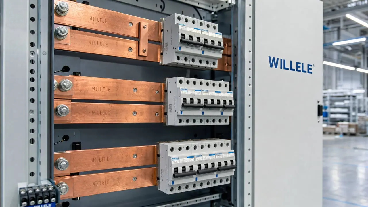
Circuit breaker busbars are metallic strips or bars—typically made of copper or aluminum—that conduct electricity within electrical distribution panels and switchgear assemblies. They serve as common connection points where multiple circuit breakers attach, allowing efficient power distribution from main supply lines to individual circuits. In manufacturing facilities, these components handle substantial current loads while maintaining electrical isolation between different circuits.
The fundamental role of busbars in circuit breaker panels is to provide a low-resistance path for electrical current. Unlike traditional wiring, busbars offer superior current-carrying capacity in a compact footprint, making them ideal for high-density electrical installations common in manufacturing environments. Their rigid construction also provides mechanical stability and reduces the risk of connection failures that can occur with flexible conductors.
Types of Busbars Used in Manufacturing
Manufacturing facilities employ various busbar configurations depending on power requirements, space constraints, and safety considerations. The most common types include:
Main Busbars: These primary conductors carry the full load from the main power source to distribution points. In large manufacturing plants, main busbars may handle currents ranging from 1,000 to 6,000 amperes or more.
Distribution Busbars: Secondary-level conductors that branch from main busbars to supply power to specific production areas or equipment zones. These typically handle 400 to 1,600 amperes.
Neutral and Ground Busbars: Essential for system safety, these busbars provide return paths for current and fault protection. They’re critical for maintaining proper grounding in industrial environments where equipment safety is paramount.
Isolated Phase Busbars: Used in high-power applications where each phase conductor is enclosed separately to minimize electromagnetic interference and enhance safety.
| Busbar Type | Typical Current Rating | Primary Application | Material Preference |
|---|---|---|---|
| Main Busbar | 1,000-6,000A | Primary distribution | Copper |
| Distribution Busbar | 400-1,600A | Secondary circuits | Copper/Aluminum |
| Neutral Busbar | Matches phase rating | Return path | Aluminum |
| Ground Busbar | 25-50% of phase rating | Safety grounding | Copper |
| Isolated Phase | 2,000-5,000A | Heavy machinery | Copper |
Material Selection: Copper vs. Aluminum
The choice between copper and aluminum busbars significantly impacts system performance, cost, and longevity. Each material offers distinct advantages for manufacturing applications.
Copper Busbars provide superior electrical conductivity (approximately 60% better than aluminum), allowing smaller cross-sectional areas for equivalent current capacity. Their excellent mechanical strength and resistance to corrosion make them ideal for harsh manufacturing environments. Copper’s higher melting point also provides better performance under fault conditions. However, copper’s higher cost and weight can be limiting factors in large installations.
Aluminum Busbars offer a cost-effective alternative, particularly for large-scale installations where budget constraints exist. While requiring larger cross-sections to match copper’s current capacity, aluminum’s lighter weight simplifies installation and reduces structural support requirements. Modern aluminum alloys with improved conductivity and surface treatments have narrowed the performance gap, making them increasingly popular in manufacturing facilities.
Design Considerations for Manufacturing Environments
Designing busbar systems for manufacturing facilities requires careful attention to multiple factors that directly impact reliability and safety.
Current Capacity and Thermal Management: Busbars must be sized to handle not only normal operating currents but also short-term overloads and fault conditions. Thermal calculations should account for ambient temperature variations in manufacturing spaces, which can range from sub-zero in cold storage facilities to extreme heat in foundries or metal processing plants. Proper spacing between busbars and adequate ventilation are essential to prevent overheating.
Mechanical Stress and Vibration: Manufacturing equipment generates significant vibration that can loosen connections and cause busbar fatigue over time. Robust mounting systems with vibration-dampening features are necessary, particularly near heavy machinery, presses, or equipment with reciprocating components.
Environmental Protection: Manufacturing environments expose electrical components to various contaminants—metal dust, chemical vapors, moisture, and temperature extremes. Busbar enclosures must provide appropriate ingress protection (IP) ratings, typically IP54 or higher for industrial applications. In particularly harsh environments such as chemical processing or food manufacturing, IP65 or IP67 ratings may be necessary.
Expansion and Flexibility: Manufacturing facilities frequently undergo equipment upgrades and layout changes. Busbar systems should incorporate expansion capacity—typically 20-30% spare capacity—to accommodate future growth without major infrastructure modifications.
Installation Best Practices
Proper installation of circuit breaker busbars is critical for long-term reliability and safety. Manufacturing facilities should adhere to established standards while considering site-specific requirements.
Surface Preparation: All busbar contact surfaces must be cleaned and prepared according to manufacturer specifications. For copper busbars, this typically involves removing oxidation and applying joint compound. Aluminum busbars require special attention to oxide layer removal and the application of anti-oxidant compounds to prevent contact resistance increase over time.
Torque Specifications: Connection bolts must be tightened to precise torque values specified by manufacturers and electrical codes. Under-tightening leads to high resistance connections that generate heat and can cause failures. Over-tightening can damage busbars or create stress concentrations. Torque wrenches calibrated to appropriate ranges are essential installation tools.
Phase Spacing and Clearances: Maintaining proper clearances between phases prevents flashover and ensures safe operation. Minimum spacing depends on voltage levels and environmental conditions. For 480V systems common in manufacturing, typical phase-to-phase spacing ranges from 25mm to 50mm, increasing for higher voltages.
Support and Mounting: Busbars require adequate mechanical support at intervals determined by their size, weight, and orientation. Horizontal runs typically need support every 600-900mm, while vertical installations may require closer spacing. Insulating supports must be rated for the system voltage and environmental conditions.
Protection and Safety Systems
Circuit breaker busbars in manufacturing facilities require comprehensive protection to prevent equipment damage and ensure personnel safety.
Overcurrent Protection: Circuit breakers connected to busbars must be properly coordinated to provide selective protection. This ensures that only the affected circuit opens during fault conditions, minimizing disruption to other manufacturing processes. Coordination studies should account for motor starting currents, transformer inrush, and other transient conditions common in industrial settings.
Ground Fault Protection: Manufacturing facilities with sensitive electronic equipment or wet processes require ground fault protection to detect and interrupt low-level ground faults that might not trip overcurrent devices. Ground fault relays with adjustable sensitivity (typically 30mA to 30A) provide this protection.
Arc Flash Mitigation: Busbars operating at high current levels present arc flash hazards during maintenance or fault conditions. Modern installations incorporate arc flash detection systems that can trip circuit breakers in milliseconds, significantly reducing incident energy. Proper labeling with arc flash boundary information and required personal protective equipment (PPE) is mandatory.
Thermal Monitoring: Advanced busbar systems include temperature sensors at critical connection points. These monitors provide early warning of developing problems such as loose connections or overload conditions before they lead to failures. Integration with facility monitoring systems enables predictive maintenance strategies.
Maintenance and Inspection Protocols
Regular maintenance of circuit breaker busbars is essential for reliable manufacturing operations. A comprehensive maintenance program should include:
Visual Inspections: Quarterly visual inspections should check for signs of overheating (discoloration, melted insulation), physical damage, corrosion, and loose connections. Thermal imaging surveys can identify hot spots indicating high-resistance connections or overloaded conductors before they fail.
Connection Tightness Verification: Annual torque checks of all bolted connections prevent failures due to thermal cycling and vibration. This is particularly important in the first year after installation as connections may settle.
Cleaning and Contamination Control: Accumulation of conductive dust or debris can create tracking paths and reduce insulation effectiveness. Periodic cleaning using appropriate methods for the environment maintains system integrity.
Insulation Resistance Testing: Megohmmeter testing verifies insulation integrity between phases and to ground. This testing should be performed annually or after any significant environmental event such as flooding or chemical exposure.
Energy Efficiency and Power Quality
Well-designed busbar systems contribute to manufacturing facility energy efficiency and power quality.
Reduced Resistive Losses: Properly sized busbars with high-quality connections minimize I²R losses. In high-current applications, even small resistance reductions can yield significant energy savings. A 1,000A busbar with 10 microohms of excess resistance wastes 10 kilowatts continuously—over 87,000 kWh annually.
Voltage Drop Minimization: Excessive voltage drop in distribution systems reduces equipment efficiency and can cause operational problems. Busbar systems should be designed to limit voltage drop to 3% or less under full load conditions.
Harmonic Mitigation: Modern manufacturing facilities with variable frequency drives and other non-linear loads generate harmonic currents. Busbar sizing must account for harmonic heating effects, which can increase effective current by 10-20% in some installations.
Integration with Modern Manufacturing Systems
Contemporary manufacturing facilities increasingly integrate electrical distribution systems with digital monitoring and control platforms.
Smart Monitoring: Digital sensors on busbars provide real-time data on current flow, temperature, and power quality. This information integrates with manufacturing execution systems (MES) to optimize production scheduling based on available electrical capacity.
Predictive Maintenance: Machine learning algorithms analyze busbar performance data to predict maintenance needs before failures occur. This approach reduces unplanned downtime and extends equipment life.
Energy Management: Detailed monitoring of busbar-level power consumption enables sophisticated energy management strategies, including load shifting, demand response participation, and identification of inefficient equipment.
Comparison: Traditional Wiring vs. Busbar Systems
| Feature | Traditional Cable Wiring | Busbar Systems |
|---|---|---|
| Current Capacity | Up to 600A practical limit | 6,000A+ readily achievable |
| Space Efficiency | Requires substantial conduit space | Compact, high-density installation |
| Installation Time | Labor-intensive pulling and termination | Faster assembly and connection |
| Modification Flexibility | Difficult to modify after installation | Easier to add or relocate connections |
| Heat Dissipation | Limited by insulation and bundling | Superior thermal performance |
| Fault Current Capability | Limited by cable construction | Excellent short-circuit withstand |
| Initial Cost | Lower for small installations | More economical for high-current applications |
| Long-term Reliability | Connection points vulnerable | Robust mechanical connections |
Regulatory Compliance and Standards
Manufacturing facilities must ensure busbar installations comply with applicable electrical codes and industry standards. In North America, the National Electrical Code (NEC) provides fundamental requirements for busbar sizing, spacing, and protection. The IEEE C37 series standards address switchgear and busbar design for industrial applications.
International facilities should reference IEC 61439 standards for low-voltage switchgear and controlgear assemblies. These standards specify design verification, temperature rise limits, and short-circuit performance requirements.
Industry-specific regulations may impose additional requirements. Food processing facilities must meet sanitation standards that affect enclosure design. Chemical plants require compliance with hazardous location classifications that dictate busbar enclosure construction and sealing methods.
Future Trends in Busbar Technology
The evolution of manufacturing technology drives innovation in busbar design and application.
Higher Voltage DC Systems: As manufacturing facilities adopt more DC-powered equipment and renewable energy sources, DC busbar systems are becoming more common. These systems require different insulation coordination and protection strategies compared to traditional AC installations.
Modular and Prefabricated Systems: Factory-assembled busbar modules reduce installation time and improve quality consistency. These systems arrive at job sites fully tested and ready for connection, minimizing field labor and commissioning time.
Advanced Materials: Research into composite conductors and advanced alloys promises improved performance characteristics. Carbon nanotube-enhanced conductors and graphene-based materials may offer superior conductivity and mechanical properties in future applications.
Integrated Sensing and Communication: Next-generation busbars incorporate embedded sensors and wireless communication capabilities, enabling real-time monitoring without external instrumentation. This integration supports Industry 4.0 initiatives and smart factory implementations.
FAQ
Q: How often should circuit breaker busbars be inspected in a manufacturing facility?
A: Visual inspections should be conducted quarterly, with comprehensive maintenance including torque checks and thermal imaging performed annually. High-vibration environments or critical processes may require more frequent inspection intervals.
Q: Can aluminum and copper busbars be directly connected?
A: Direct connection of aluminum and copper creates galvanic corrosion issues. Use bimetallic transition plates or connectors specifically designed for this purpose, with appropriate anti-oxidant compounds applied to all contact surfaces.
Q: What is the typical lifespan of industrial busbars?
A: With proper installation and maintenance, copper busbars can last 30-40 years or more. Aluminum busbars typically have a 25-35 year service life. Environmental conditions and loading patterns significantly affect longevity.
Q: How do I calculate the required busbar size for my facility?
A: Busbar sizing requires calculating total connected load, applying appropriate demand factors, adding safety margins (typically 25%), and considering ambient temperature and installation conditions. Consult with qualified electrical engineers and reference NEC Article 366 or applicable local codes.
Q: What causes busbar overheating, and how can it be prevented?
A: Common causes include loose connections, undersized conductors, excessive harmonic currents, and inadequate ventilation. Prevention strategies include proper initial sizing, regular torque verification, thermal monitoring, and maintaining adequate clearances for heat dissipation.
