Railway Signaling Systems: Cable Lug Requirements and Standards
A single loose cable lug in a railway signaling cabinet can halt an entire line. When trains run at two-minute headways through a busy urban corridor, a failed termination at a trackside junction box doesn’t just trigger a maintenance call — it cascades into delays, safety protocol activations, and regulatory scrutiny. This is why railway signaling systems impose requirements on their cable lugs that go well beyond what commercial and even most industrial applications demand.
For procurement engineers and signaling system integrators, selecting the right cable lug means navigating a landscape of overlapping European, international, and national standards — each addressing a different dimension of performance: mechanical integrity under vibration, electrical conductivity under thermal cycling, fire behavior in enclosed tunnel environments, and long-term corrosion resistance in exposed wayside installations. This article maps that landscape and explains what each standard requires, so you can specify cable lugs that keep your signaling infrastructure connected and compliant.
Why Railway Signaling Demands More from a Cable Lug
A cable lug in a typical industrial panel experiences a relatively stable environment: controlled temperature, minimal vibration, and predictable maintenance intervals. The same component on a railway signaling installation faces a fundamentally different set of conditions.
Vibration is the most obvious stressor. Trackside equipment cabinets and underfloor junction boxes on rolling stock are subjected to continuous low-frequency vibration from passing trains, plus occasional shock loads during coupling and braking. EN 61373 defines the vibration and shock testing regimes for railway equipment; cable lugs used in these applications must maintain their crimp integrity through the full test profile without loosening, cracking, or developing excessive contact resistance.
Temperature cycling is equally demanding. A cable lug bolted to a busbar inside a lineside location case may see surface temperatures swing from -25°C on a winter night to over 70°C under full electrical load on a summer afternoon. Repeated thermal expansion and contraction works the crimp interface microscopically: copper and the tin or silver plating expand at slightly different rates, and if the crimp compression was inadequate to begin with, the joint will gradually relax, increasing resistance and generating heat — a feedback loop that ends in thermal runaway.
Then there is the electromagnetic environment. Railway signaling cables run parallel to traction power feeders carrying thousands of amps, often for kilometers. Without proper shielding continuity through every termination — including the cable lug’s connection to the cable screen — induced currents can corrupt the low-level DC or coded AC signals that keep trains separated. EN 50121-4 defines the EMC emission and immunity requirements for signaling equipment; the cable lug is a critical node in maintaining that electromagnetic integrity.
Add to this the fire safety demands of tunnel and metro operations, where halogen-free materials and low-smoke, zero-halogen (LSZH) insulation systems are mandatory, and the cable lug’s plating material and any insulating sleeve become part of the fire performance equation.
Standards That Govern Cable Lugs in Railway Signaling
The standards framework for cable lugs in railway signaling is not a single document but a stack of references, each addressing a different layer of the problem. The table below summarizes the principal standards and what each one covers.
| Standard | Scope | What It Means for Cable Lug Selection |
|---|---|---|
| EN 50125-1 | Environmental conditions for railway equipment | Defines temperature, humidity, and pollution classes that cable lugs must withstand |
| EN 50155 / IEC 60571 | Electronic equipment on rolling stock | Mandates shock/vibration and temperature cycling performance for all electrical connections |
| EN 61373 | Vibration and shock testing | Provides the test profiles cable lug assemblies must survive without degradation |
| EN 50121-4 | EMC for signaling and telecom equipment | Requires screen continuity and low-impedance terminations to maintain shielding |
| EN 45545-2 / IEC 60332-3 | Fire behavior of materials on rolling stock | Sets flammability, smoke density, and toxicity limits for insulating sleeves and plating |
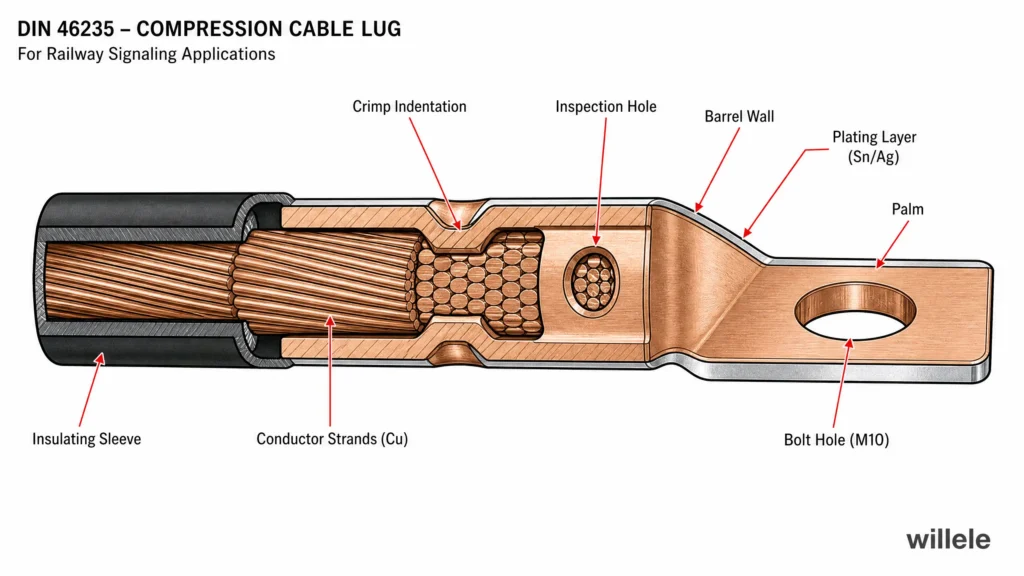
| DIN 46235 | Compression cable lugs — dimensions and marking | Defines barrel dimensions, marking requirements, and application ranges for copper lugs |
| DIN 48083-4 | Crimping dies for compression connections | Specifies hexagonal die geometry and die-code matching to conductor cross-section |
| IEC 61238-1 | Mechanical and electrical test requirements for compression connectors | Defines the test sequence — mechanical pull-out, electrical resistance, and heat cycling — that qualifies a lug-conductor combination |
| BS 7609 / BS 7727 | British codes of practice for crimping and inspection | Covers installation procedures, tool calibration, and visual inspection criteria |
| EN 13600 | Copper for electrical purposes | Sets purity and mechanical property requirements for the copper used in cable lug bodies |
What this table reveals is that specifying a cable lug for railway signaling is not a single product selection — it is a system-level decision that ties together the conductor material, the lug’s copper grade and plating, the crimping die profile, the tool calibration regime, and the final inspection protocol. A lug that meets DIN 46235 dimensionally but is installed with a mismatched die or insufficient compression will still fail, and neither the lug manufacturer nor the tool supplier will carry the liability alone.
Material and Design: What the Standards Require
The starting point for any railway signaling cable lug is the copper. EN 13600 mandates electrolytic-tough-pitch (ETP) copper with a minimum conductivity of 100% IACS (International Annealed Copper Standard) and tightly controlled oxygen content. This ensures consistent electrical performance and predictable deformation behavior under the crimping die. Some manufacturers also offer oxygen-free high-conductivity (OFHC) copper for applications where hydrogen embrittlement is a concern — relevant in environments with prolonged exposure to moisture or certain chemical atmospheres.
Plating is the next decision point. Standard tin plating provides adequate corrosion protection for most indoor and sheltered outdoor installations, but railway signaling equipment is often located in coastal corridors, industrial zones, or tunnel environments with elevated humidity and airborne contaminants. Silver plating offers lower contact resistance and better performance at elevated temperatures, making it the preferred choice for high-reliability signaling terminations where even a few milliohms of additional resistance can degrade signal integrity. The plating thickness must balance corrosion protection against cost: a minimum of 5 μm of tin or 3 μm of silver is typical for railway-grade lugs.
DIN 46235 defines three categories of compression cable lugs relevant to signaling applications: standard tubular lugs for stranded conductors up to Class 2, F-type lugs with a flared entry and enlarged inner diameter for flexible Class 5 and Class 6 conductors, and sheet-metal terminals for smaller cross-sections in control wiring. Each type carries mandatory markings — manufacturer identifier, conductor cross-section range, bolt size, and, critically, the number and position of crimp indentations. These markings are not cosmetic; they are the installer’s guide to achieving a compliant termination, and their absence on a lug should disqualify the part for railway use.
For the insulating sleeve, where one is used, the material must comply with the relevant fire performance standard for the installation environment. In rolling stock applications, EN 45545-2 sets hazard levels (HL1 to HL3) based on the vehicle type and operating conditions; any polymeric component on the cable lug, including heat-shrink identification sleeves, must meet the applicable HL requirements for flammability, smoke density, and toxicity.
Crimping: The Standard That Matters Most in the Field
A cable lug that meets every material and dimensional standard is still only as good as the crimp that attaches it to the conductor. This is where the greatest number of field failures originate, and where the standards framework provides the most detailed guidance.
DIN 48083-4 specifies hexagonal crimping dies for copper compression lugs from 6 mm² to 1,000 mm², with each die marked with the conductor cross-section range, die code, and a “Cu” designation confirming it is intended for copper lugs. The standard requires that the die, lug, and conductor be matched as a system: using the correct die code for the given lug and conductor cross-section is mandatory, not advisory. An undersized die over-compresses the barrel, thinning the wall and potentially fracturing the copper; an oversized die leaves voids between the conductor strands and the barrel wall, creating hot spots under load.
The number of crimp indentations is specified by the lug manufacturer and marked on the lug body. For a typical 35 mm² signaling cable lug, this might be two compressions; for a 150 mm² power feeder lug, four or more. Each indentation must start from the palm side and progress toward the barrel end, ensuring that any surplus conductor length is pushed forward rather than trapped at the crimp entry, where it could create a stress concentration.
The table below shows recommended die codes and crimp counts for common railway signaling conductor sizes.
| Conductor Cross-Section (mm²) | Typical Application | DIN 48083-4 Die Code | Recommended Crimp Count | Die Width (mm) |
|---|---|---|---|---|
| 1.5 – 2.5 | Point machine control wiring | 5 – 6 | 2 | 5 |
| 4 – 6 | Signal head power supply | 8 – 10 | 2 | 5 |
| 10 – 16 | Track circuit feed | 12 – 14 | 2 – 3 | 7 |
| 25 – 35 | Power distribution within location cases | 16 – 20 | 3 | 7 |
| 50 – 70 | Axle counter / interlocking supply | 22 – 25 | 3 – 4 | 8 |
| 95 – 120 | Main signaling power feeder | 28 – 30 | 4 | 10 |
| 150 – 185 | Substation to signaling equipment room | 34 – 38 | 4 – 5 | 12 |
BS 7609, the British code of practice for installing compression connectors, adds process requirements that are particularly relevant to railway project quality assurance: tools must be calibrated and the calibration recorded, dies must be inspected for wear before each shift, a sample crimp must be made at the start of each batch and cross-sectioned to verify compression quality, and the inspection results must be traceable to the individual installer, tool, and lug batch. In practice, railway signaling contractors often exceed BS 7609 by requiring pull-test verification on a statistical sample from every installation shift, with the acceptance criterion drawn from IEC 61238-1.
Testing and Verification
IEC 61238-1 defines the qualification test sequence for compression connectors, and it is the benchmark against which any cable lug intended for railway signaling should be evaluated. The standard requires three sequential tests on the same sample:
- Mechanical pull-out test: The lug is subjected to a tensile force that must not cause separation below a specified minimum, typically 60% of the conductor’s rated breaking strength for copper lugs. This verifies that the crimp has achieved adequate mechanical interlock between the barrel and the conductor strands.
- Electrical resistance test: The resistance across the crimp joint is measured using a four-wire Kelvin method and compared against the resistance of an equivalent length of unbroken conductor. The ratio must not exceed 1.0 — in other words, the crimp joint must not add measurable resistance.
- Heat cycling test: The assembly is subjected to repeated cycles of heating (by passing rated current) and cooling to ambient, typically 500 or 1,000 cycles, while resistance and temperature are monitored continuously. Any upward trend in resistance indicates progressive degradation of the crimp interface and is grounds for rejection.
For railway-specific qualification, these tests are often extended: the heat cycling may be performed with superimposed vibration matching the EN 61373 profile, and salt-mist exposure per IEC 60068-2-52 may be introduced between cycles to simulate coastal or de-icing salt environments.
Common Failure Modes and How Standards Prevent Them
The standards framework exists because the failure modes are well understood and each one can be prevented — but only if the standards are applied as an integrated system, not as a checklist of isolated requirements.
Incomplete conductor insertion occurs when the stripped conductor does not fully bottom out in the lug barrel before crimping. The result is a partial crimp that grips only the forward portion of the conductor, leaving the rear strands loose and prone to pulling out under tension. DIN 46235 lugs address this with inspection holes in the barrel that allow the installer to verify full insertion visually before crimping begins.
Die mismatch produces a crimp that is either under-compressed (high initial resistance, rapid thermal degradation) or over-compressed (thinned barrel wall, risk of cracking under vibration). The DIN 48083 die-marking system, combined with the lug manufacturer’s compression markings, eliminates guesswork — but only if the installer follows the markings rather than relying on experience or feel.
Corrosion at the contact interface between the lug palm and the busbar or terminal stud is a particular risk in wayside installations where condensation, de-icing chemicals, or coastal salt spray are present. Silver-plated lugs mated to silver-plated busbars provide the most reliable long-term interface, while tin-plated lugs on tin-plated busbars are adequate for sheltered installations. Mixed-metal interfaces — tin on silver, or copper on aluminium — must be avoided or protected with an appropriate jointing compound, as galvanic corrosion will progressively increase contact resistance and may eventually cause overheating.
Overtightening of the bolted connection is a field error that no lug standard directly prevents, but its effects — deformation of the palm, thread stripping, and eventual loosening under vibration — can be mitigated by specifying lugs with an appropriate palm thickness for the bolt size and by following the torque values specified in the equipment manufacturer’s documentation rather than the installer’s calibrated arm.
Selecting Cable Lugs for Railway Signaling Projects
For a signaling system integrator or railway infrastructure contractor, the selection process reduces to a sequence of decisions, each mapped to a standard:
- Define the environmental class from EN 50125-1 — outdoor exposed, sheltered outdoor, indoor controlled, or tunnel — to determine the corrosion protection and temperature range required.
- Identify the conductor class (stranded Class 2, flexible Class 5, or extra-flexible Class 6) and select a lug type that matches — standard tubular for Class 2, F-type for Class 5/6.
- Verify the copper grade and plating against the environmental class: tin for dry indoor, silver for outdoor/tunnel/coastal.
- Confirm the lug is marked per DIN 46235 with manufacturer ID, conductor range, bolt size, and crimp count; reject unmarked lugs regardless of other claims.
- Match the crimping die to the lug using the DIN 48083-4 die-code table; verify the die is calibrated and in good condition before use.
- Execute the crimp per the lug manufacturer’s compression sequence, working from palm to barrel end.
- Inspect and test per BS 7609/BS 7727, with pull-test verification on a sample basis where project specifications require it.
- Record traceability data: lug batch, tool and die identification, installer name, date, and test results — linked to the installation location for future maintenance reference.
willele manufactures a comprehensive range of compression cable lugs purpose-built for railway signaling applications, with full material traceability from EN 13600-compliant copper, silver and tin plating options, and DIN 46235-compliant marking. Every batch is qualified to IEC 61238-1 electrical and mechanical performance requirements. Our technical team provides die-matching guidance and onsite crimping support for signaling contractors and system integrators working to EN 50125, EN 50155, and EN 45545-2 requirements.
Frequently Asked Questions
What is the difference between a standard tubular cable lug and an F-type lug?
Standard tubular lugs per DIN 46235 are designed for stranded conductors up to Class 2, where the conductor is relatively rigid and the strands are large enough that the lug barrel grips them effectively. F-type lugs have a wider inner diameter and a flared entry to accommodate flexible Class 5 and Class 6 conductors, which have finer strands and compress differently under the crimping die. Using a standard lug on a flexible conductor will likely result in an under-filled barrel and a weak crimp.
Can I use the same cable lug for trackside and onboard signaling installations?
Not necessarily. While the lug body may be identical, the environmental conditions differ: onboard installations on rolling stock are subject to EN 45545-2 fire performance requirements that may restrict insulating sleeve materials, and the vibration profile per EN 61373 differs from trackside installations. Always verify that the complete assembly — lug, sleeve, and identification marking — meets the standards applicable to the specific installation location.
How often should crimping tools be calibrated for railway signaling work?
BS 7609 recommends calibration at intervals not exceeding 12 months, but many railway signaling specifications reduce this to 6 months or require re-calibration after any incident where the tool may have been damaged. A pre-shift go/no-go gauge check on the die is standard practice, with the result recorded in the installation log alongside the tool serial number.
Does IEC 61238-1 qualification guarantee performance in railway environments?
IEC 61238-1 qualifies the electrical and mechanical performance of the lug-conductor combination under laboratory conditions. It does not test for vibration, salt-mist corrosion, or fire behavior. For railway signaling applications, the qualification must be supplemented with additional testing against EN 61373 (vibration), EN 50125-1 (environmental), and, where applicable, EN 45545-2 (fire). Ask your lug supplier for test reports covering the full railway-specific profile, not just the generic IEC qualification.
What marking should I look for on a DIN 46235-compliant cable lug?
A properly marked lug will show the manufacturer’s identifier, the conductor cross-section range (e.g., “35–50” for 35 mm² to 50 mm²), the bolt size (e.g., “M10”), and the required number of crimps. Some manufacturers also mark the recommended die code directly on the lug. If any of these markings is missing, the lug does not comply with DIN 46235 and should not be used on a railway signaling installation.
