Application of Flame Retardant Tubing in High Voltage Cabling

High voltage cabling carries the backbone of modern power distribution—from substation switchgear rated at 35 kV, to renewable energy inverters, EV charging infrastructure, and industrial bus ducts running at tens of kilovolts. At these voltages, a single insulation failure can trigger arc flashes, sustained fires, and cascading equipment damage. Flame retardant tubing is the engineered barrier that stands between reliable operation and catastrophe: a heat-shrinkable or extruded sleeve that insulates live conductors, suppresses flame propagation, and maintains dielectric integrity under thermal stress.
For B2B specifiers—panel builders, EPC contractors, and utility engineers—selecting the right flame retardant tubing is a design decision with direct consequences for safety certification, insurance underwriting, and long-term service life. This article examines how flame retardant tubing functions in high voltage applications, the material and standards landscape, and the selection criteria that separate compliant installations from liability.
Why Flame Retardant Tubing Matters in HV Systems
In a high voltage environment, the failure mode is not gradual. When insulation breaks down at 35 kV, the energy released in the resulting arc can exceed 40 MJ within milliseconds—enough to vaporize copper, ignite adjacent cable jackets, and propagate fire along an entire cable tray. The role of flame retardant tubing is twofold: it provides the primary dielectric insulation that prevents flashover, and it introduces a self-extinguishing material barrier that stops flame from traveling along the cable run once ignited elsewhere.
The “flame retardant” designation is not marketing language. It refers to a specific, tested behavior: the tubing must cease burning within a defined period after the ignition source is removed. This is verified through standardized vertical flame tests such as UL 224 VW-1, where a specimen is subjected to a 500 W flame for 15 seconds, removed, and re-applied for another 15 seconds. The tubing passes if it self-extinguishes within 60 seconds, the indicator tissue paper below does not ignite, and no flaming drips occur.
In high voltage cabling specifically, flame retardant tubing serves three functions simultaneously: dielectric insulation (preventing current leakage and flashover between phase conductors and ground), environmental sealing (blocking moisture, salt fog, and chemical ingress that degrade insulation over decades), and fire containment (limiting flame spread so that a localized fault does not become a system-wide fire).
Material Technologies: What the Tubing Is Made Of
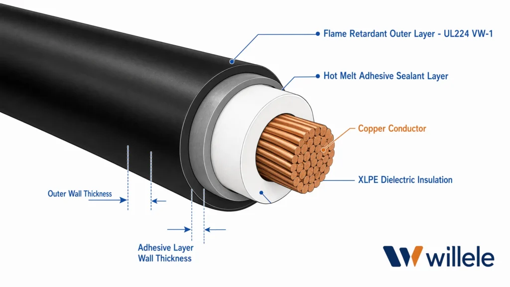
Cross-section of dual-wall flame retardant tubing over an HV cable conductor. Image: willele.
The performance of flame retardant tubing is determined almost entirely by its base polymer and the flame retardant additive package. Four material families dominate the high voltage landscape:
| Material | Temp. Range | Dielectric Strength | Key HV Application | Flame Rating |
|---|---|---|---|---|
| Cross-linked Polyolefin (XLPO) | −55°C to +135°C | 20–25 kV/mm | Busbar insulation, 1–35 kV switchgear | UL 224 VW-1 |
| Fluoropolymer (PTFE/FEP) | −65°C to +260°C | 60–120 kV/mm | Aerospace, extreme-environment HV | UL 94 V-0 |
| Silicone Rubber | −60°C to +200°C | 18–23 kV/mm | High-temperature terminations | UL 94 V-1/V-0 |
| PVC (Plasticized) | −20°C to +105°C | 14–20 kV/mm | Low-voltage harnessing, ≤600 V | UL 224 VW-1 |
Cross-linked polyolefin is the workhorse of high voltage cabling. The cross-linking process—typically achieved through electron beam radiation—creates a three-dimensional molecular network that does not melt at elevated temperatures. This is critical: a non-crosslinked polyolefin would soften and flow at 130°C, losing its dielectric gap. The crosslinked version maintains mechanical and electrical integrity even when the conductor runs hot under peak load.
For applications above 35 kV, thick-wall XLPO busbar tubing is specified. The rule of thumb in HV insulation design is approximately 1 mm of wall thickness per 1 kV of system voltage for rigid insulation; heat-shrink tubing, which conforms tightly and eliminates air voids, can achieve comparable performance at thinner profiles. Products such as 3M’s BBI-A series and TE Connectivity’s Raychem BBIT line cover the 5–35 kV and up to 72 kV ranges respectively, using specially formulated track-resistant XLPO compounds.
Dual-wall constructions add a hot-melt adhesive inner liner. When the tubing shrinks, the adhesive melts and flows, filling voids between the tubing and the irregular surface of a cable joint or connector. This creates an environmental seal rated for long-term immersion and salt-spray exposure—essential for outdoor HV installations and offshore platforms.
Standards and Compliance Framework
Selecting flame retardant tubing without referencing the governing standard is a specification error. The following table maps the standards most relevant to high voltage cabling:
| Standard | Scope | Test Method | Typical Application |
|---|---|---|---|
| UL 224 | Insulating tubing, general | VW-1 vertical flame, 600 V | Internal wiring, appliances |
| IEC 60684 | Flexible insulating sleeving | Flame test per Part 1; material specs per Part 3 | European/global HV markets |
| ASTM D2671 | Heat-shrinkable tubing | Hot mandrel, low-temp flexibility, dielectric | Military/aerospace, North America |
| IEC 60332-1/3 | Vertical flame propagation | Single cable / bunched cable flame test | Cable runs in trays and conduits |
| EN 45545-2 | Railway fire protection | Fire load, smoke, toxicity | Rolling stock HV cabling |
| ANSI C37.20.2 | MV switchgear insulation | Power frequency withstand, impulse | 5–38 kV metal-clad switchgear |
The UL 224 VW-1 rating and IEC 60684 compliance are the baseline for any flame retardant tubing entering a high voltage installation. For railway and transit applications, EN 45545-2 adds smoke density and toxic gas emission limits—halogenated flame retardants, while effective, are restricted in these environments because they release corrosive hydrogen chloride and dense smoke when burned. Halogen-free flame retardant (HFFR) formulations, using metal hydroxides such as aluminum trihydrate (ATH) or magnesium dihydroxide (MDH), are increasingly specified in enclosed spaces where occupant evacuation is a factor.
For switchgear insulation, ANSI C37.20.2 is the North American benchmark. It defines the power frequency withstand voltage, impulse withstand, and partial discharge requirements that busbar insulation must meet to be accepted in metal-clad switchgear assemblies rated 5 kV through 38 kV.
Application Scenarios in High Voltage Cabling
Busbar Insulation in MV Switchgear
The most widespread use of flame retardant tubing in high voltage systems is busbar insulation within medium-voltage switchgear. Bare copper or aluminum busbars carry phase-to-phase voltages at 12 kV, 24 kV, or 36 kV, and the air gap alone is the only insulation between phases and the grounded enclosure. Applying thick-wall flame retardant tubing over each busbar allows designers to reduce phase spacing, shrink the overall enclosure footprint, and add a critical layer of personnel protection against accidental contact. The tubing must withstand not only the continuous operating voltage but also the transient overvoltages from switching surges and lightning impulses.
Cable Termination and Joint Protection
At cable terminations—where the shield is stripped back and the conductor exits into a lug or connector—the cable’s built-in insulation is interrupted. Flame retardant tubing, often in combination with stress control tubing, restores the insulation envelope and provides the environmental seal that prevents moisture ingress at the most vulnerable point in the cable system. Dual-wall adhesive-lined tubing is standard here, as the adhesive fills the irregular geometry of the stripped cable transition.
Renewable Energy and EV Infrastructure
Solar farm combiner boxes, wind turbine nacelle wiring, and DC fast-charging stations all involve high-voltage DC cabling in outdoor or semi-outdoor environments. Flame retardant tubing in these applications must survive UV exposure, thermal cycling from −40°C to +85°C ambient, and the mechanical stresses of vibration and thermal expansion. XLPO tubing with UV stabilizers and adhesive lining is the typical specification.
Installation: Where Compliance Is Won or Lost
A flame retardant tubing product that meets every standard on paper can still fail in service if the installation is wrong. The most common failure mode is incomplete recovery—tubing that has not fully shrunk, leaving air voids between the tubing and the conductor surface. These voids become sites for partial discharge at high voltage, which erodes the insulation over months or years and eventually causes flashover.
Proper installation requires a controlled heat source—typically a propane torch or a high-output hot air gun—applied evenly from the center of the tubing outward to the ends. This pushes trapped air ahead of the shrinking front and ensures full contact. The installer must verify that the tubing has reached its full recovery temperature (usually 120°C for polyolefin) across the entire surface, not just at the heated spot. For adhesive-lined tubing, the visual indicator of proper installation is adhesive flow at both ends, forming a smooth fillet.
On thick-wall busbar tubing, the shrink process can take several minutes per meter. Rushing the heat application causes surface scorching without full underlying recovery—a defect that is invisible to casual inspection but detectable through partial discharge testing.
Selection Guide: Matching Tubing to the Application
| Selection Factor | Question to Ask | Recommended Approach |
|---|---|---|
| Voltage rating | What is the system’s max operating voltage? | Select tubing rated ≥125% of max operating voltage |
| Temperature | What is the worst-case conductor temperature? | XLPO for ≤135°C; silicone or fluoropolymer for higher |
| Environment | Indoor switchgear or outdoor exposure? | Dual-wall adhesive-lined for outdoor/wet; single-wall for dry indoor |
| Flame standard | Which compliance regime applies? | UL 224 VW-1 (NA); IEC 60684 (EU/global); EN 45545-2 (rail) |
| Halogen content | Is the installation in an occupied enclosed space? | Specify HFFR for rail, tunnels, and occupied buildings |
| Shrink ratio | What is the range of object diameters to cover? | 2:1 for uniform busbars; 3:1 or 4:1 for connectors and transitions |
| Wall thickness | What dielectric margin is required? | 1 kV/mm guideline for rigid; confirm via partial discharge test |
Frequently Asked Questions
Q1: What is the difference between flame retardant and fire resistant tubing?
Flame retardant tubing is designed to self-extinguish after the ignition source is removed—it limits flame spread but does not guarantee continued circuit operation during a fire. Fire resistant tubing (and fire resistant cable systems) maintains circuit integrity for a defined period under direct flame exposure, typically 30–120 minutes per IEC 60331. For high voltage cabling, flame retardant tubing is the standard specification; fire resistance is a separate system-level requirement.
Q2: Can flame retardant tubing be used on cables rated above 35 kV?
Yes, but material selection and wall thickness become critical. Track-resistant XLPO tubing is available for applications up to 72 kV, and fluoropolymer tubing handles even higher voltages due to its superior dielectric strength. At these voltages, the tubing is typically part of an engineered termination system that includes stress control layers, not a standalone insulation product.
Q3: Are halogen-free flame retardant tubes as effective as halogenated ones?
Halogen-free formulations using ATH or MDH additives achieve UL 94 V-0 and VW-1 ratings, but they typically require higher filler loadings, which can reduce flexibility and elongation. For most HV cabling applications, the performance gap is acceptable, and the smoke and toxicity benefits in enclosed spaces make HFFR the preferred choice for rail, tunnel, and building installations.
Q4: How long does flame retardant tubing last in service?
Quality XLPO flame retardant tubing has a design service life of 20–30 years in typical indoor switchgear environments. Outdoor service life depends on UV stabilization and adhesive performance—well-formulated dual-wall products can exceed 25 years in temperate climates. Accelerated aging testing per IEC 60216 is used to verify the claimed service life.
Q5: Does willele offer flame retardant tubing certified for HV applications?
Yes. willele manufactures flame retardant heat shrink tubing across single-wall (HTS) and dual-wall adhesive-lined (HTD) families, with formulations meeting UL 224 VW-1, IEC 60684, and RoHS/REACH requirements. Products are available in shrink ratios from 2:1 to 4:1, with voltage ratings up to 35 kV for busbar insulation applications. Full datasheets, COC documentation, and lot traceability are provided for B2B procurement and audit support.
