
MNS Series Busbar Insulator — Willele
Cylindrical MNS busbar insulators for LV/MV switchboards, MCCs, rectifiers, ESS DC buses and control panels.
Compression-molded BMC/SMC body with plated brass/steel inserts ensures dependable insulation and rigid clamping.
Full diameter/height matrix from Ø16~Ø70 mm with multiple threads; customization for color and compound grade.
Introduction to MNS Series Busbar Insulators
Willele MNS Series busbar insulators combine robust electrical insulation with rigid mechanical support for copper or aluminum busbars. The compact cylindrical profile fits dense layouts and stacked bars, enabling standardized mounting heights and thread sizes while preserving clean creepage paths.
Each insulator is compression-molded from BMC/SMC with a plated metal insert. The structure delivers repeatable tightening torque, dimensional stability under vibration/thermal cycling, and long service life in low- to medium-voltage equipment.
Function and Purpose of Willele MNS Insulators
Electrical insulation: the molded body acts as a non-conductive barrier that reduces phase-to-phase faults and arcing. Mechanical support: the threaded insert and core geometry provide a rigid mounting point to keep bars aligned during vibration and short-circuit forces.
Willele MNS Series Overview
Key Features
- High-quality BMC/SMC construction for durability and strength
- Operating temperature range: −40 °C to +140 °C (compound dependent)
- Brass or steel threaded inserts with protective plating for corrosion resistance
- Customizable color, insert type and material grade to match project needs
- Built to international practices for consistent performance
Typical Uses
LV/MV switchgear, MCCs, rectifier & inverter cabinets, ESS/DC bus assemblies, transformer connections and industrial control panels.
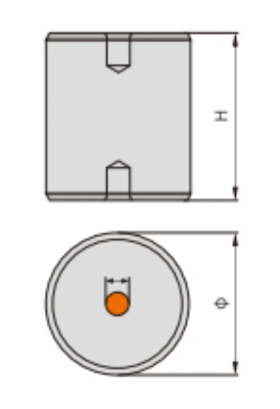
Key Specifications and Size Matrix
Typical values below. Confirm final ratings and tolerances with Willele before design-in.
| TYPE | DIAMETER (mm) | HEIGHT (mm) | SCREW (mm) | SCREW DEPTH (mm) |
|---|---|---|---|---|
| MNS16 | Φ16 | 20, 25, 30, 35, 40 | M6 | 8 |
| MNS20 | Φ20 | 20, 25, 30, 35, 40 | M6 | 8 |
| MNS25 | Φ25 | 25, 30, 40, 50 | M6 | 9 |
| MNS30 | Φ30 | 30, 40, 50, 60 | M8 | 9 |
| MNS40 | Φ40 | 40, 50, 60, 70, 80 | M8, M10 | 12 |
| MNS50 | Φ50 | 50, 60, 70, 80 | M8, M10 | 15 |
| MNS60 | Φ60 | 60, 70, 80, 90 | M10, M12 | 15 |
| MNS70 | Φ70 | 70, 80, 90, 100, 110 | M14, M16 | 18, 22 |
Dimensions and Size Chart
Electrical and Mechanical Notes
Electrical
- Choose a model whose dielectric withstand exceeds operating level and expected transients.
- Verify creepage/clearance in the cabinet layout.
- Outdoor-grade compounds on request.
Mechanical
- Match screw size and thread depth to clamps and base plates.
- Apply the recommended tightening torque; re-check after initial thermal cycle if required.
- Align bars so forces are axial to the insert; avoid prying loads.
Ordering Information
Please provide: type/diameter & height (e.g., MNS50 × 60), insert material (brass/steel), quantity & destination, and any certification/inspection needs. Optional: color, special compound, packaging.


