
SB Series Busbar Insulator — Willele
Hexagonal (A/F) busbar insulators for LV/MV switchboards, MCCs and control cabinets.
Compression-molded BMC/SMC body with plated brass/steel inserts for firm clamping and stable insulation.
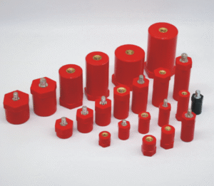
Size matrix from A/F 20–60 mm, multiple heights and thread options; colors and material grades customizable.
Introduction to SB Series Busbar Insulators
Willele SB Series busbar insulators use a hexagonal A/F profile for easy wrench access and controlled tightening torque. They provide reliable electrical isolation and rigid mechanical support for copper or aluminum busbars in space-constrained cabinets and stacked-bar layouts.
Each unit is compression-molded from BMC/SMC with a plated metal insert, delivering repeatable tightening torque, dimensional stability under vibration/thermal cycling, and long-term service in low- to medium-voltage assemblies.
Function and Purpose
Electrical insulation: the molded body acts as a non-conductive barrier to reduce phase-to-phase faults and arcing. Mechanical support: the threaded insert and hex body create a rigid mounting point so busbars remain aligned during vibration and short-circuit forces.
Willele SB Series Overview
Key Features
- Compression-molded BMC/SMC body for mechanical strength and dielectric stability
- Typical operating range: −40 °C to +140 °C (compound dependent)
- Brass or steel threaded inserts with protective plating for corrosion resistance
- Hexagonal A/F profile for secure wrenching and torque control
- Customization for color, insert type, thread, height and compound grade
Typical Applications
LV/MV switchgear, MCCs, rectifier & inverter cabinets, ESS/DC bus assemblies, transformer connections and industrial control panels.
Specifications
| TYPE | A/F (mm) | HEIGHT (mm) | TORQUE (ft-lbs) | SCREW (mm) |
|---|---|---|---|---|
| SB20 | 20 | 20, 25, 30, 40, 50 | 5 | 5, 6 |
| SB30 | 30 | 30, 35, 40, 50, 60, 65 | 10 | 6, 8 |
| SB35 | 35 | 45 | 35 | 10 |
| SB40 | 40 | 35, 40, 50, 60, 70 | 16 | 8, 10 |
| SB60 | 60 | 40, 50, 60, 70, 80 | 50 | 12, 16 |
Dimensions and Size Chart
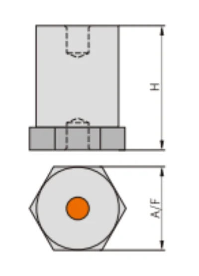
Electrical and Mechanical Notes
Electrical
- Select a model whose dielectric withstand comfortably exceeds operating level and expected transients.
- Verify creepage and clearance in the cabinet layout.
- Outdoor-grade compounds available on request.
Mechanical
- Match screw size and thread depth to clamps and base plates.
- Apply the recommended tightening torque; re-check after initial thermal cycle if required.
- Align bars so forces are axial to the insert; avoid prying loads on the hex shoulder.
Ordering Information
For a fast quote and drawing, please provide: type and size (e.g., SB40, A/F 40 × H 50), thread and insert material (brass/steel), quantity & destination, and any certification/inspection needs. Optional: color, special compound, packaging.