
Willele WLB Modular Distribution Blocks
Industrial connector boxes with insulated PA66 base (UL94 V-2) and clear PC cover
Brass busbars for low-loss distribution; zinc-plated screw hardware
DIN-plate M4 mounting (45/80/112 mm) with compact footprints
Wide temperature endurance: PA66 −30~110 °C; PC −60~135 °C
Overview
The WLB Modular Distribution Blocks provide compact, safe and tidy power distribution with an insulated back plate and a transparent protective front cover. They can be mounted on DIN rail or fixed by two screws, and every busbar can be labelled using 3TM. These blocks comply with EN 60947-1 and withstand an ICC peak of 20 kA. Wiring is supported with or without ferrules, covering common conductor cross-sections in industrial panels.
Materials: brass busbars with zinc-plated hardware, PC clear cover, insulated back plate. Ratings include 125 A models (2-bar & 4-bar) and a heavy-duty 160 A model.
Key Features
- Connection with or without ferrules; per-bar insulation protection.
- Two mounting methods: DIN-rail clip or plate fixing with 2 screws.
- Transparent PC front cover; insulated back plate; self-extinguishing design.
- Each bar individually labelable (3TM) for quick circuit identification.
- EN 60947-1 compliant; ICC 20 kA peak withstand.
- Seven models: 2-bar (WLB-207/211/215), 4-bar (WLB-407/411/415), and 3-bar heavy-duty (WLB-413).
- Compact footprints from 65×42×50 mm up to 168×138×73 mm.
- Clean, professional wiring layouts for multi-circuit distribution.
modular distribution blocks Specifications
| Item No. | Rated Current (A) | Bus Bar Spec. | No. of Bus Bar | Conductors with starfix ferrules — X-section (mm²) | Conductors without ferrules — X-section (mm²) | Dimensions (L × W × H) (mm) |
|---|---|---|---|---|---|---|
| WLB-207 | 125 | 5×Ø5.3 mm; 2×Ø7.5 mm | 2 | 1.5–6; 6–16 | 2.5–6; 10–25 | 65 × 42 × 50 |
| WLB-211 | 125 | 7×Ø5.3 mm; 2×Ø7.5 mm; 2×Ø9 mm | 2 | 1.5–6; 6–16; 10–16 | 2.5–6; 10–25; 10–35 | 100 × 42 × 50 |
| WLB-215 | 125 | 11×Ø5.3 mm; 2×Ø7.5 mm; 2×Ø9 mm | 2 | 1.5–6; 6–16; 10–16 | 2.5–6; 10–25; 10–35 | 133 × 42 × 50 |
| WLB-407 | 125 | 5×Ø5.3 mm; 2×Ø7.5 mm | 4 | 1.5–6; 6–16 | 2.5–6; 10–25 | 65 × 88 × 50 |
| WLB-411 | 125 | 7×Ø5.3 mm; 2×Ø7.5 mm; 2×Ø9 mm | 4 | 1.5–6; 6–16; 10–16 | 2.5–6; 10–25; 10–35 | 100 × 88 × 50 |
| WLB-415 | 125 | 11×Ø5.3 mm; 2×Ø7.5 mm; 2×Ø9 mm | 4 | 1.5–6; 6–16; 10–16 | 2.5–6; 10–25; 10–35 | 133 × 88 × 50 |
| WLB-413 | 160 | 8×Ø7.5 mm; 4×Ø9 mm; 1×Ø12 mm | 4 | 6–16; 10–16; 25–35 | 10–25; 10–35; 35–50 | 168 × 138 × 73 |
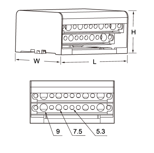
Notes: “Bus Bar Spec.” lists the hole diameters per bar; conductor ranges show typical cross-sections supported with/without ferrules.
Dimension
Applications
- Power distribution inside control panels, machinery and switchboards.
- Lighting, HVAC, and general building services distribution.
- Multi-circuit OEM equipment wiring with clear labelling per bar.
FAQ
A: They conform to EN 60947-1 and can withstand ICC 20 kA peak.
A: Either on DIN-rail or by fixing to a plate with two screws.
A: Yes. The table lists cross-sections for both ferruled and non-ferruled conductors.
A: 2-bar models are compact for single-source branching; 4-bar models suit 3P+N layouts;
Download Resources


