Busbars in Commercial Building Electrical Design
In modern commercial building electrical systems, the efficient and reliable distribution of power is paramount. At the heart of these distribution networks lies a critical component that often goes unnoticed yet plays an indispensable role: the busbar. Circuit breaker busbars, in particular, have revolutionized how electrical contractors and engineers approach power distribution in commercial facilities, offering a streamlined alternative to traditional wiring methods while enhancing safety, reliability, and installation efficiency.
Understanding Circuit Breaker Busbars
A circuit breaker busbar, also known as a comb busbar or MCB busbar, is a metallic conductor strip specifically engineered to interconnect multiple miniature circuit breakers within distribution panels and consumer units. These rigid conductive bars serve as the backbone of electrical distribution systems, facilitating the transfer of electrical power from a main incoming source to multiple circuit breakers, which then protect individual circuits or loads throughout the building.
Unlike conventional cable-based distribution methods that require extensive individual wire runs, busbars consolidate multiple electrical connections into a centralized hub. This fundamental design principle transforms complex power distribution into an organized, efficient system that reduces installation time, minimizes potential failure points, and simplifies maintenance procedures.
The busbar system integrates seamlessly with circuit breakers through standardized connection methods, creating a robust and serviceable electrical distribution architecture suitable for residential, commercial, and light industrial applications. The result is a power distribution solution that addresses the growing demands of modern commercial buildings while maintaining the highest safety standards.
Material Composition and Construction
The performance and longevity of circuit breaker busbars depend heavily on their material composition. Modern busbars typically utilize two primary conductive materials: copper and aluminum, each offering distinct advantages for different applications.
Copper Busbars remain the gold standard for high-performance electrical distribution. Electrolytic Tough Pitch (ETP) copper, containing at least 99.90% pure copper, delivers excellent electrical conductivity and reasonable corrosion resistance. The superior conductivity of copper allows for smaller cross-sectional areas to carry equivalent current loads compared to aluminum, making copper busbars ideal for space-constrained installations.
Aluminum Busbars provide a cost-effective alternative where weight reduction and budget constraints are primary considerations. While aluminum’s electrical conductivity is approximately 61% that of copper, its significantly lower density (about one-third of copper’s weight) makes it advantageous for large-scale installations where structural load becomes a factor.
The conductive metal strips are typically enclosed in high-quality insulating materials, most commonly engineered plastics or thermosetting resins. This combination ensures efficient power distribution while maintaining rigorous safety standards and preventing accidental contact with live conductors.
Types of Circuit Breaker Busbar Connections
Commercial building electrical design requires flexibility in how circuit breakers connect to busbars. Two primary connection types dominate the market:
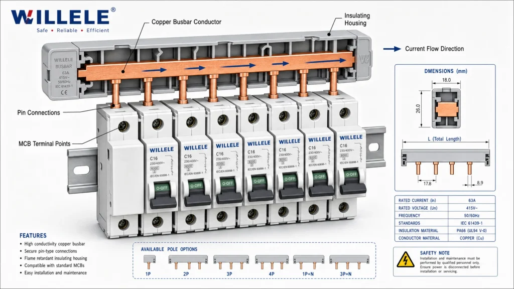
Pin-Type (Comb) Busbars feature specially designed fingers or pins that extend outwardly from the conductive bar, precisely spaced to match the center spacing of circuit breakers. This comb-like structure allows miniature circuit breakers to snap directly onto the busbar through innovative quick-release technology. The pin-type design is particularly prevalent in residential and light commercial applications where standardized MCB spacing (typically 18mm modules) is common.
Fork-Type Busbars utilize forked terminals (typically M5 or M6) that bolt directly to MCB terminal screws, providing a bolted connection method suitable for a wider range of breaker types. This configuration offers universal compatibility with most standard MCBs, making it highly versatile for panel builders working with various breaker brands and models. The fork terminals create robust mechanical and electrical connections through proper torque application, ensuring low contact resistance and reliable performance under thermal cycling conditions.
Busbar Configurations in Commercial Systems
The architectural layout of busbar systems significantly impacts system reliability, maintenance flexibility, and operational continuity. Commercial buildings typically employ one of several standard configurations:
Single Busbar Systems represent the simplest and most economical configuration, where all circuit breakers connect to a single continuous busbar. This straightforward design minimizes component count and installation complexity, making it ideal for smaller commercial facilities or applications where brief service interruptions during maintenance are acceptable.
Split Busbar Systems divide the distribution panel into two or more independent sections, each fed by separate busbars. This configuration enhances system reliability by allowing one section to remain operational while maintenance is performed on another. Split bus arrangements are particularly valuable in commercial buildings with critical loads that cannot tolerate complete power loss.
Ring Busbar Configurations create a closed-loop system where power can flow from multiple directions. If one circuit experiences issues, the system continues operating through alternate paths. This design localizes faults to specific segments and permits maintenance without interrupting the entire supply, though the closed-circuit topology may limit future expansion possibilities.
Key Advantages in Commercial Applications
The adoption of circuit breaker busbars in commercial building electrical design stems from numerous practical advantages:
Installation Efficiency: Busbar systems dramatically reduce installation time compared to traditional point-to-point wiring. Instead of running individual wires to each circuit breaker, electricians simply snap or bolt breakers onto the pre-installed busbar, cutting labor costs by 30-50% in typical commercial panel installations.
Space Optimization: The compact profile of busbars allows for higher circuit density within distribution panels. This space efficiency is particularly valuable in commercial buildings where electrical room real estate comes at a premium.
Enhanced Safety: By eliminating numerous wire terminations, busbars reduce potential connection failures and hot spots. The insulated construction prevents accidental contact with live conductors, while the standardized connection methods minimize installation errors.
Simplified Maintenance: The organized layout of busbar-fed circuit breakers facilitates faster troubleshooting and circuit identification. Technicians can quickly locate and service individual circuits without navigating through complex wire bundles.
System Expandability: Modern busbar systems support modular expansion, allowing facility managers to add circuits as building requirements evolve without major panel reconfiguration.
Current Capacity and Sizing Considerations
Proper busbar sizing is critical for safe and efficient commercial electrical distribution. Busbars are available in standard current ratings ranging from 40 to 1,250 amperes, with popular commercial options including 100A, 250A, and 800A configurations.
The current-carrying capacity of a busbar depends on multiple factors:
- Cross-sectional area: Larger cross-sections reduce electrical resistance and heat generation
- Material conductivity: Copper’s superior conductivity allows smaller dimensions for equivalent current ratings
- Ambient temperature: Higher operating temperatures reduce effective current capacity
- Installation method: Enclosed busbars require derating due to reduced cooling
- Duty cycle: Continuous loads require more conservative sizing than intermittent loads
For commercial building applications, engineers typically apply a safety factor of 125% to calculated load currents, ensuring adequate capacity for future growth and preventing thermal stress during peak demand periods.
Comparison: Busbars vs. Traditional Wiring
| Feature | Circuit Breaker Busbars | Traditional Cable Wiring |
|---|---|---|
| Installation Time | 30-50% faster | Baseline (100%) |
| Labor Cost | Significantly lower | Higher due to termination time |
| Space Requirements | Compact, high-density | Requires more panel space |
| Connection Reliability | Standardized, consistent | Varies with installer skill |
| Maintenance Access | Excellent visibility | Difficult in dense wire bundles |
| Expansion Flexibility | Modular, easily extended | Requires significant rework |
| Material Cost | Moderate to high initial | Lower initial material cost |
| Long-term Reliability | Fewer failure points | More terminations = more risk |
| Heat Dissipation | Superior due to mass | Limited by insulation |
| Fault Localization | Easier to isolate | Time-consuming to trace |
Integration with Modern Circuit Protection
Circuit breaker busbars are designed for seamless compatibility with modern protective devices from major manufacturers including ABB, Siemens, Schneider Electric, Eaton, and Allen Bradley. This universal compatibility ensures that electrical contractors can specify equipment based on performance requirements rather than connection limitations.
The standardized mounting dimensions and connection interfaces allow for mixed-brand installations when necessary, providing procurement flexibility and competitive pricing advantages. However, for optimal performance and warranty compliance, many engineers prefer to maintain brand consistency within individual panels.
Design Considerations for Commercial Buildings
When specifying circuit breaker busbars for commercial building electrical systems, several critical factors warrant careful consideration:
Load Analysis: Comprehensive load calculations must account for connected equipment, diversity factors, and anticipated future expansion. Commercial buildings often experience load growth over time, making oversizing busbars by 20-30% a prudent investment.
Voltage Drop: While busbars exhibit lower resistance than equivalent cable runs, voltage drop calculations remain essential, particularly in large distribution panels or systems with long busbar runs. Maintaining voltage drop below 3% ensures optimal equipment performance.
Short Circuit Capacity: Busbars must withstand the mechanical and thermal stresses of fault conditions. The short-circuit withstand rating should exceed the available fault current at the installation point, typically verified through coordination studies.
Environmental Factors: Commercial building environments vary widely. HVAC equipment rooms experience temperature extremes, while food service areas may expose electrical equipment to moisture and corrosive cleaning agents. Busbar selection must account for these environmental stresses through appropriate material selection and protective coatings.
Accessibility and Serviceability: Panel layout should provide adequate working clearance around busbars, complying with electrical codes while facilitating safe maintenance procedures. Front-access designs are increasingly popular in commercial applications where rear access is impractical.
Material Selection: Copper vs. Aluminum
| Property | Copper Busbars | Aluminum Busbars |
|---|---|---|
| Electrical Conductivity | 100% (reference) | ~61% of copper |
| Thermal Conductivity | Excellent | Good |
| Weight | Heavy (8.96 g/cm³) | Light (2.70 g/cm³) |
| Corrosion Resistance | Excellent | Requires protective coating |
| Mechanical Strength | High | Moderate |
| Cost | Higher initial investment | Lower material cost |
| Cross-section Required | Smaller for same current | Larger (approximately 1.6×) |
| Thermal Expansion | Lower coefficient | Higher coefficient |
| Connection Reliability | Superior long-term | Requires anti-oxidant compound |
| Typical Applications | High-density panels, critical systems | Large installations, weight-sensitive |
Installation Best Practices
Proper installation of circuit breaker busbars is essential for long-term system reliability and safety. Professional electricians should adhere to these fundamental practices:
Torque Specifications: All bolted connections must be tightened to manufacturer-specified torque values. Under-tightening leads to high resistance connections and potential hot spots, while over-tightening can damage terminals or strip threads.
Surface Preparation: Contact surfaces should be clean and free from oxidation, paint, or contamination. For aluminum busbars, application of anti-oxidant compound prevents oxide layer formation that increases contact resistance.
Alignment and Support: Busbars must be properly supported at specified intervals to prevent mechanical stress from short-circuit forces. Insulators should be rated for the system voltage with adequate creepage and clearance distances.
Phase Identification: Clear phase marking (typically A-B-C or L1-L2-L3) prevents connection errors and facilitates future maintenance. Color coding or permanent labels should be applied according to local electrical codes.
Testing and Commissioning: Before energization, comprehensive testing should include insulation resistance measurements, continuity verification, and thermal imaging during initial load application to identify any high-resistance connections.
Thermal Management and Heat Dissipation
Electrical resistance in busbars generates heat proportional to the square of the current (I²R losses). In commercial applications with sustained high loads, thermal management becomes critical for preventing premature failure and maintaining safe operating temperatures.
The thermal performance of busbars benefits from their solid construction and large surface area, which facilitates natural convection cooling. However, enclosed panel environments limit air circulation, requiring careful attention to panel ventilation design. Many modern commercial panels incorporate forced ventilation or heat dissipation strategies to maintain acceptable operating temperatures.
Thermal imaging during commissioning and periodic maintenance helps identify developing problems before they cause failures. Hot spots typically indicate high-resistance connections requiring immediate attention.
Standards and Compliance
Circuit breaker busbars used in commercial building electrical design must comply with numerous international and regional standards:
- IEC 61439: Low-voltage switchgear and controlgear assemblies
- UL 67: Panelboards standard (North America)
- IEC 60529: Ingress protection (IP) ratings for enclosures
- NEC Article 408: Switchboards and panelboards (United States)
- BS EN 61439: British/European standards for distribution assemblies
Compliance with these standards ensures that busbar systems meet minimum safety requirements for construction, testing, and performance. Specifying certified products from reputable manufacturers like Willele provides assurance of regulatory compliance and quality construction.
Future Trends and Innovations
The evolution of commercial building electrical systems continues to drive busbar technology forward. Several emerging trends are shaping the future of circuit breaker busbars:
Smart Integration: Next-generation busbars incorporate sensors for real-time monitoring of current, voltage, temperature, and power quality. This data integration supports predictive maintenance strategies and energy management systems.
Sustainable Materials: Environmental considerations are driving research into recyclable materials and manufacturing processes with reduced carbon footprints. The inherent recyclability of copper and aluminum busbars aligns well with circular economy principles.
Modular Systems: Increasingly sophisticated modular busbar systems allow for rapid reconfiguration as building uses change, supporting the flexible workspace concepts prevalent in modern commercial architecture.
Enhanced Safety Features: Arc-fault detection, ground-fault monitoring, and advanced insulation materials continue to improve the safety profile of busbar systems in commercial applications.
Conclusion
Circuit breaker busbars represent a mature yet continually evolving technology that addresses the fundamental challenges of commercial building electrical distribution. Their combination of installation efficiency, space optimization, reliability, and safety makes them the preferred choice for modern commercial facilities ranging from office buildings and retail centers to industrial facilities and data centers.
For electrical contractors, engineers, and facility managers, understanding the technical characteristics, application considerations, and best practices surrounding circuit breaker busbars is essential for designing and maintaining robust electrical distribution systems. As commercial buildings become increasingly complex and energy-intensive, the role of properly specified and installed busbar systems in ensuring reliable, safe, and efficient power distribution will only grow in importance.
Willele Electric, with our expertise in electrical component manufacturing and commitment to quality, provides circuit breaker busbars and related products that meet the demanding requirements of modern commercial electrical systems. Our focus on precision manufacturing and rigorous testing ensures that our products deliver the reliability and performance that commercial applications demand.
Frequently Asked Questions (FAQ)
Q: What is the typical lifespan of circuit breaker busbars in commercial buildings?
A: Properly installed and maintained copper or aluminum busbars typically last 25-40 years in commercial environments. The actual lifespan depends on operating conditions, load cycling, environmental factors, and maintenance quality. Regular thermal imaging and connection inspections can identify potential issues before they lead to failures.
Q: Can I mix different brands of circuit breakers on the same busbar?
A: While many busbars offer universal compatibility with standard DIN-rail MCBs, mixing brands is generally not recommended. Different manufacturers may have subtle variations in contact design that affect performance. For optimal reliability and warranty coverage, maintain brand consistency within each panel.
Q: How do I determine the correct busbar current rating for my commercial building?
A: Calculate the total connected load, apply appropriate demand factors based on building type and usage patterns, then add a 25% safety margin for future expansion. Consult with a licensed electrical engineer for complex installations or buildings with critical loads.
Q: What maintenance is required for circuit breaker busbar systems?
A: Annual visual inspections should check for signs of overheating, loose connections, or physical damage. Every 3-5 years, perform thermal imaging under load to identify high-resistance connections. Retorque bolted connections according to manufacturer schedules, typically every 5 years or after any significant electrical event.
Q: Are aluminum busbars suitable for commercial building applications?
A: Yes, aluminum busbars are widely used in commercial buildings, particularly in larger installations where weight and cost are considerations. However, aluminum requires proper connection techniques including anti-oxidant compound and may need larger cross-sections than copper equivalents. For high-density panels or critical applications, copper remains the preferred choice.
Q: What is the difference between pin-type and fork-type busbars?
A: Pin-type (comb) busbars allow circuit breakers to snap directly onto protruding pins, offering fast installation for standard modular MCBs. Fork-type busbars use bolted connections with forked terminals, providing universal compatibility with various breaker types and more robust connections for higher current applications. Choose based on breaker compatibility and installation requirements.
