
Commercial Building Power Distribution with Busbar Insulators

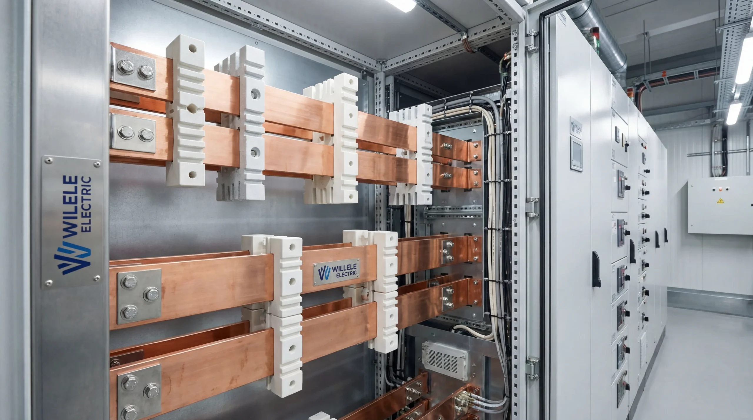
In modern commercial buildings, reliable power distribution systems form the backbone of daily operations. From office towers to shopping centers, manufacturing facilities to data centers, the safe and efficient delivery of electrical power depends on carefully engineered components working in harmony. Among these critical components, busbar insulators play an essential yet often overlooked role in maintaining system integrity and preventing catastrophic failures.
Busbar insulators serve as the protective barrier between high-voltage conductors and grounded surfaces, ensuring that electrical current flows only where intended. These specialized components must withstand extreme electrical stress, thermal cycling, mechanical loads, and environmental conditions while maintaining their insulating properties over decades of service. Understanding their function, selection criteria, and proper application is fundamental to designing power distribution systems that meet both safety standards and operational demands.
Understanding Busbar Systems in Commercial Applications
Commercial building power distribution relies on busbar systems to efficiently transfer large amounts of electrical current from the main service entrance to various distribution points throughout the facility. Unlike traditional cable-based systems, busbars consist of solid copper or aluminum conductors that offer superior current-carrying capacity, reduced voltage drop, and simplified installation in confined spaces.
The typical commercial building employs a hierarchical distribution architecture. Power enters through the main service equipment, flows through primary distribution busbars rated for hundreds or thousands of amperes, then branches into secondary distribution systems serving specific floors or zones. At each connection point, junction, and support location, busbar insulators maintain the critical separation between energized conductors and structural elements.
Figure 1: Willele Electric busbar insulator product range showing various sizes and configurations for different voltage and current ratings
Modern busbar systems operate at voltages ranging from 480V in typical three-phase distribution to 15kV in medium-voltage applications. The insulation requirements scale dramatically with voltage, requiring careful material selection and geometric design to prevent surface tracking, internal breakdown, and flashover events that could disable entire building sections.
The Critical Role of Busbar Insulators
Busbar insulators perform multiple simultaneous functions that directly impact system safety and reliability. Their primary purpose involves providing electrical isolation between conductors operating at different potentials, preventing short circuits that would trigger protective devices and interrupt power to critical loads. This isolation must remain effective across the full range of operating conditions, from initial energization through decades of thermal cycling and mechanical stress.
Beyond basic insulation, these components provide mechanical support for heavy copper or aluminum busbars that may weigh several pounds per linear foot. The insulator must securely anchor the conductor while accommodating thermal expansion that can amount to several millimeters over a multi-meter span. This mechanical function requires materials with excellent compressive strength and dimensional stability across temperature ranges from -40°C to +130°C or higher.
Environmental protection represents another crucial function. Busbar insulators shield connection points from moisture, dust, and chemical contaminants that could compromise insulation resistance. In coastal installations, salt fog resistance becomes paramount. Industrial facilities may require resistance to oils, solvents, or corrosive gases. The insulator material and surface finish must maintain their protective properties throughout the system’s design life, typically 30 to 40 years for commercial installations.
Material Science Behind High-Performance Insulators
The selection of insulation materials fundamentally determines system performance and longevity. Modern busbar insulators employ several material families, each offering distinct advantages for specific applications.
Thermoset Composite Materials
Dough molding compound (DMC) and sheet molding compound (SMC) represent the most widely used materials in commercial busbar insulators. These thermoset polyester composites combine unsaturated polyester resin with glass fiber reinforcement, mineral fillers, and specialized additives. The molding process creates a dense, void-free structure with excellent electrical properties and mechanical strength.
DMC insulators exhibit dielectric strength exceeding 20 kV/mm, tracking resistance rated CTI 600, and continuous operating temperatures up to 155°C. The material’s inherent flame resistance meets UL94 V-0 requirements without additional treatment. Glass fiber content typically ranges from 15% to 30% by weight, providing the mechanical strength needed to support heavy busbars under seismic loads.
SMC formulations offer even higher performance for demanding applications. With glass fiber content reaching 50% by weight in directional reinforcement patterns, SMC insulators achieve superior mechanical properties while maintaining excellent electrical characteristics. The material’s low water absorption (less than 0.1% by weight) ensures stable performance in humid environments.
Epoxy Resin Systems
Cycloaliphatic epoxy resins provide premium performance where extreme conditions demand the highest reliability. These materials offer exceptional tracking resistance (CTI 600+), superior arc resistance, and outstanding long-term stability. Epoxy insulators maintain their properties across temperature ranges from -60°C to +155°C, making them ideal for outdoor installations and environments with extreme temperature cycling.
The molecular structure of epoxy resins provides inherent resistance to ultraviolet degradation, a critical advantage for outdoor switchgear and rooftop installations. Unlike some thermoplastic materials that become brittle with UV exposure, properly formulated epoxy insulators maintain their mechanical properties for decades of outdoor service.
Thermoplastic High-Performance Polymers
For specific applications requiring exceptional chemical resistance or extreme temperature capability, thermoplastic materials such as polyetherimide (PEI) or polyphenylene sulfide (PPS) offer unique advantages. These materials can operate continuously at temperatures exceeding 180°C, making them suitable for applications with high ambient temperatures or significant I²R heating from busbar current.
| Material Type | Dielectric Strength (kV/mm) | CTI Rating | Max Operating Temp (°C) | Water Absorption (%) | Typical Applications |
|---|---|---|---|---|---|
| DMC (Polyester) | 18-22 | 600 | 155 | 0.15-0.25 | General commercial distribution |
| SMC (Polyester) | 20-25 | 600 | 155 | 0.08-0.15 | High mechanical load applications |
| Cycloaliphatic Epoxy | 25-30 | 600+ | 155 | 0.05-0.10 | Outdoor, high-reliability systems |
| Mineral-Filled Epoxy | 22-28 | 600+ | 180 | 0.10-0.20 | Medium voltage applications |
| PEI Thermoplastic | 20-24 | 600 | 200 | 0.25-0.35 | High-temperature environments |
Design Considerations for Commercial Installations
Selecting appropriate busbar insulators requires careful analysis of multiple interrelated factors. The design process begins with establishing the electrical requirements based on system voltage, current rating, and fault current magnitude. These parameters determine the minimum creepage and clearance distances required by applicable standards.
Electrical Specifications
Creepage distance—the shortest path along the insulator surface between conductors at different potentials—must meet or exceed values specified in IEC 60664-1 or UL 840 based on the system voltage and pollution degree. For a 480V system in a clean indoor environment (Pollution Degree 2), minimum creepage distance is 6.3mm. Industrial environments with conductive dust (Pollution Degree 3) require 10mm. Medium-voltage systems at 15kV demand creepage distances exceeding 160mm.
Clearance distance represents the shortest direct air path between conductors. This dimension must account for the system’s impulse withstand voltage, which depends on the installation altitude, overvoltage category, and transient protection measures. Commercial buildings typically fall under Overvoltage Category III, requiring clearances that can withstand 6kV impulse voltages for 480V systems.
The insulator’s comparative tracking index (CTI) indicates its resistance to surface tracking caused by contamination and moisture. Materials with CTI ratings of 600 or higher (Material Group I) provide the best long-term reliability in commercial applications where maintenance intervals may extend to several years between inspections.
Mechanical Requirements
Busbar insulators must support both static loads from the conductor weight and dynamic loads from fault currents, seismic events, and thermal expansion. A 4-inch wide copper busbar rated for 3000A weighs approximately 6.4 pounds per foot. Over a six-foot span between supports, each insulator must carry roughly 19 pounds of static load while maintaining precise positioning.
Short-circuit forces present a far more severe challenge. When fault current flows through parallel busbars, electromagnetic forces attempt to push the conductors apart. For a 65kA fault current in busbars spaced 2 inches apart, the repulsive force reaches approximately 1700 pounds per foot of length. Insulators must withstand these momentary forces without cracking or allowing conductor displacement that could create additional faults.
Seismic requirements vary by geographic location and building importance factor. In high-seismic zones (Seismic Design Category D or higher), insulators must meet qualification testing per IEEE 693 or IEC 60068-2-57. This testing subjects the complete assembly to simulated earthquake motion, verifying that insulators maintain their integrity and positioning throughout the event.
Thermal Management
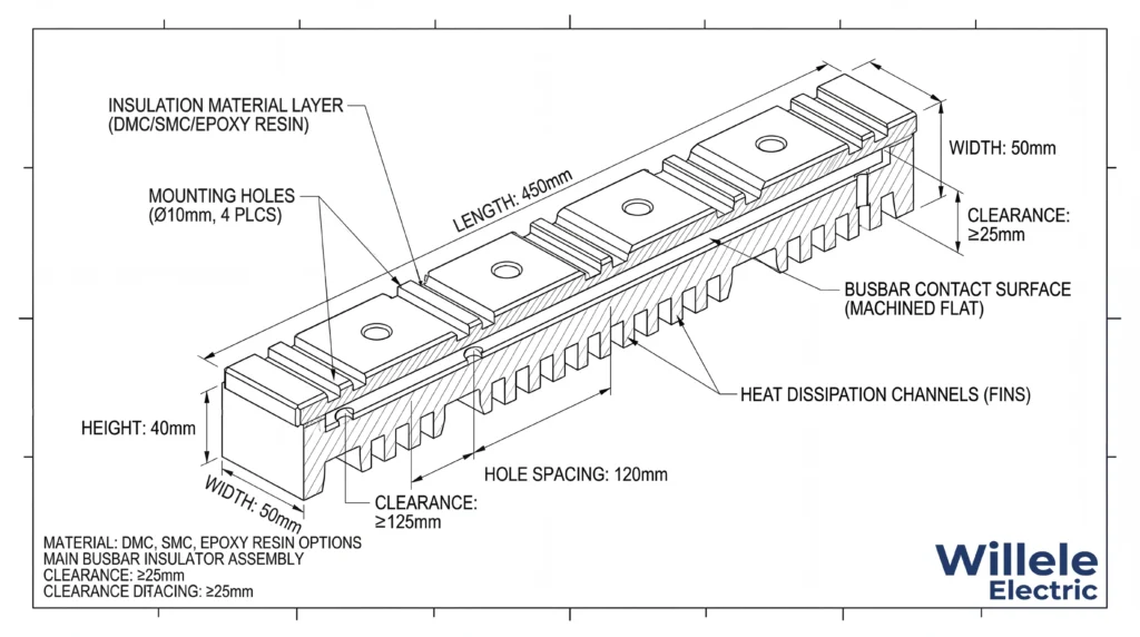
Electrical current flowing through busbar conductors generates heat through resistive losses. This heat must dissipate to the surrounding environment to prevent excessive temperature rise that could damage insulation, reduce conductor capacity, or create safety hazards. Busbar insulators directly impact thermal performance by affecting heat transfer from the conductor to mounting surfaces.
Materials with higher thermal conductivity facilitate heat dissipation, allowing higher current ratings for a given conductor size. However, this must be balanced against electrical insulation requirements—materials that conduct heat well often exhibit reduced dielectric strength. Modern insulator designs optimize this trade-off through geometric features such as increased surface area, ventilation channels, and strategic placement of thermally conductive fillers that maintain electrical properties.
Temperature rise calculations must account for ambient conditions, enclosure ventilation, and adjacent heat sources. In a typical switchgear lineup, multiple busbar sections may operate simultaneously, creating localized hot spots where air circulation is restricted. Insulators in these locations require materials rated for continuous operation at temperatures 20°C to 30°C above the nominal ambient temperature.
Installation Best Practices
Proper installation of busbar insulators is as critical as correct specification. Even premium components will fail prematurely if installed incorrectly, while proper installation practices can extend service life and improve system reliability.
Surface Preparation
All mounting surfaces must be clean, flat, and free from burrs or sharp edges that could concentrate mechanical stress. Metal surfaces should be treated to prevent corrosion, using zinc-rich primer or other protective coatings compatible with the insulator material. Any surface irregularities exceeding 0.5mm should be corrected through grinding or shimming to ensure uniform load distribution.
Before installing insulators, verify that mounting holes align properly and that hardware threads are clean and undamaged. Misaligned holes that require force during assembly create stress concentrations that can lead to cracking. Thread damage that prevents proper torque application results in loose connections that may vibrate or overheat during operation.
Torque Specifications
Mounting hardware must be tightened to manufacturer-specified torque values using calibrated tools. Under-torquing allows movement that can cause fretting corrosion and eventual mechanical failure. Over-torquing creates excessive compressive stress that may crack the insulator or cause delayed failure through stress relaxation.
For M8 mounting bolts in DMC insulators, typical torque specifications range from 8 to 12 N⋅m. Larger M10 bolts require 15 to 20 N⋅m. These values assume clean, dry threads with no lubrication. If thread lubricant is used, reduce torque by approximately 20% to prevent over-compression.
Apply torque in a controlled sequence, gradually tightening fasteners in a star pattern to ensure even load distribution. For insulators with multiple mounting points, bring all fasteners to 50% of final torque, then 75%, then 100% in successive passes. This technique prevents distortion and ensures optimal stress distribution.
Conductor Attachment
When attaching busbars to insulators, ensure that contact surfaces are clean and properly prepared. Remove any oxidation from aluminum busbars using a stainless steel brush and apply joint compound immediately to prevent re-oxidation. Copper busbars should be cleaned with a lint-free cloth and solvent to remove any oils or contamination.
Position conductors carefully to avoid side-loading insulators. Lateral forces from misaligned busbars create bending moments that significantly reduce the insulator’s load-carrying capacity. If alignment issues exist, correct them through proper support spacing or conductor forming rather than forcing components into position.
Maintenance and Inspection Protocols
Regular inspection and maintenance of busbar insulators ensures continued reliable operation and allows early detection of potential problems before they cause failures. Inspection frequency depends on the operating environment, with harsh conditions requiring more frequent examination.
Visual Inspection
Annual visual inspections should examine insulators for cracks, chips, discoloration, or surface tracking. Cracks typically appear at stress concentration points such as mounting holes or sharp corners. Even small cracks can propagate under thermal cycling and mechanical stress, eventually causing complete failure.
Surface tracking manifests as dark, carbonized paths across the insulator surface, usually between conductors at different potentials. This condition indicates that the creepage distance is inadequate for the actual pollution level, or that contamination has accumulated to dangerous levels. Any evidence of tracking requires immediate investigation and remediation.
Discoloration may indicate overheating from excessive current, poor connections, or inadequate ventilation. Brown or black discoloration near conductor contact points suggests connection problems requiring immediate attention. Uniform yellowing of white insulators typically results from UV exposure and does not necessarily indicate functional degradation, though it may warrant material testing to verify continued performance.
Thermal Imaging
Infrared thermography provides valuable insight into busbar system health without requiring shutdown or physical contact. Regular thermal surveys, conducted under representative load conditions, establish baseline temperature patterns and reveal developing problems through temperature anomalies.
Insulators operating significantly hotter than adjacent identical units may indicate loose connections, inadequate ventilation, or internal degradation. Temperature differences exceeding 15°C compared to similar components under similar loads warrant investigation. Hot spots at mounting points suggest loose hardware or inadequate torque application.
Electrical Testing
Periodic insulation resistance testing verifies that insulators maintain adequate dielectric properties. Using a megohmmeter rated for the system voltage, measure resistance between conductors and ground. Values should exceed 1000 megohms for new installations and remain above 100 megohms for in-service equipment. Declining trends in insulation resistance, even if absolute values remain acceptable, may indicate moisture absorption or contamination requiring attention.
For critical systems, consider power factor testing to detect internal degradation not visible through insulation resistance measurements alone. This technique identifies moisture ingress, contamination, and material deterioration at early stages when corrective action can prevent failures.
Comparative Analysis: Busbar Insulators vs. Alternative Solutions
When designing commercial power distribution systems, engineers must evaluate various approaches to conductor support and insulation. Understanding the advantages and limitations of each option enables informed decisions that optimize system performance, cost, and reliability.
| Feature | Busbar with Insulators | Insulated Cable | Cast Resin Bus | Air-Insulated Bus |
|---|---|---|---|---|
| Current Density | Excellent (2-3 A/mm²) | Good (1.5-2 A/mm²) | Excellent (2-3 A/mm²) | Very Good (2-2.5 A/mm²) |
| Space Efficiency | Excellent | Moderate | Good | Poor |
| Installation Flexibility | Moderate | Excellent | Low | Low |
| Maintenance Access | Excellent | Poor | Moderate | Excellent |
| Initial Cost | Moderate | Low | High | Moderate-High |
| Fault Current Rating | Excellent (>100 kA) | Limited (25-65 kA) | Excellent (>100 kA) | Good (65-100 kA) |
| Thermal Performance | Excellent | Moderate | Good | Excellent |
| Modification Ease | Good | Moderate | Poor | Good |
| Service Life | 40+ years | 25-30 years | 40+ years | 40+ years |
The busbar-with-insulators approach offers superior performance for main distribution applications where high current capacity, excellent fault current withstand, and long service life justify the moderate initial cost. The modular nature of insulated busbar systems facilitates future modifications as building loads evolve, a critical advantage in commercial facilities where tenant changes and equipment upgrades occur regularly.
Standards and Compliance Requirements
Commercial busbar installations must comply with multiple overlapping standards addressing electrical safety, fire protection, seismic resilience, and environmental performance. Understanding these requirements ensures that specified components meet all applicable criteria.
North American Standards
The National Electrical Code (NEC) Article 368 governs busway installations, establishing minimum requirements for conductor sizing, support spacing, and overcurrent protection. While the NEC does not directly specify insulator properties, it references UL 857 (Busways) and UL 840 (Insulation Coordination Including Clearances and Creepage Distances for Electrical Equipment), which contain detailed requirements for insulating materials and component spacing.
UL 840 establishes minimum creepage and clearance distances based on system voltage, pollution degree, and material group. Compliance requires testing to verify tracking resistance (CTI), proof tracking voltage (PTI), and comparative tracking index under wet conditions. Insulators must maintain their properties after exposure to heat, humidity, and thermal cycling specified in the standard.
International Standards
IEC 61439 (Low-Voltage Switchgear and Controlgear Assemblies) provides comprehensive requirements for busbar systems in commercial applications. Part 1 establishes general rules, while Part 2 addresses power switchgear and controlgear assemblies specifically. These standards require type testing to verify temperature rise, short-circuit withstand, and dielectric properties under standardized conditions.
IEC 60664-1 specifies insulation coordination for equipment within low-voltage systems, establishing clearance and creepage requirements based on overvoltage category, pollution degree, and material group. The standard’s approach differs somewhat from UL 840, occasionally requiring larger spacing for equivalent conditions. Systems intended for international markets must satisfy the more stringent requirement.
Environmental and Safety Certifications
Modern commercial buildings increasingly require environmental certifications such as LEED, BREEAM, or local green building standards. These programs may award points for using materials with low environmental impact, including insulators manufactured from recycled content or using processes with reduced emissions.
RoHS (Restriction of Hazardous Substances) compliance ensures that insulators contain no lead, mercury, cadmium, hexavalent chromium, or restricted flame retardants above specified thresholds. REACH (Registration, Evaluation, Authorization, and Restriction of Chemicals) compliance, required for European markets, restricts substances of very high concern (SVHCs) in electrical components.
Troubleshooting Common Issues
Understanding typical failure modes and their root causes enables rapid diagnosis and effective corrective action when problems occur.
Surface Tracking and Flashover
Surface tracking develops when contamination creates conductive paths across insulator surfaces. This condition typically progresses gradually, beginning with minor surface erosion and advancing to complete carbonized tracks that can carry significant current. Contributing factors include inadequate creepage distance for the pollution level, accumulation of conductive dust or chemical residues, and moisture condensation on contaminated surfaces.
Prevention requires selecting insulators with appropriate CTI ratings for the environment, maintaining adequate creepage distances per applicable standards, and implementing regular cleaning protocols in harsh environments. Once tracking begins, affected insulators must be replaced—cleaning cannot restore the damaged surface.
Mechanical Failure
Cracking or fracture of insulators typically results from excessive mechanical stress, improper installation, or material degradation. Immediate causes include over-torqued mounting hardware, side-loading from misaligned conductors, or impact during installation or maintenance. Long-term degradation may result from thermal cycling, UV exposure, or chemical attack in harsh environments.
Investigation of mechanical failures should examine mounting torque, conductor alignment, support spacing, and environmental conditions. If multiple insulators fail in similar locations, systematic issues such as inadequate support spacing or excessive fault current forces likely exist, requiring design modifications rather than simple component replacement.
Thermal Degradation
Excessive operating temperature causes gradual degradation of insulator materials, reducing mechanical strength and electrical properties. Discoloration, surface crazing, and eventual cracking indicate thermal damage. Root causes include inadequate ventilation, excessive current density, poor connections creating localized heating, or ambient temperatures exceeding design limits.
Thermal problems require comprehensive investigation of the entire system. Verify that actual load current does not exceed design values, check all connections for proper torque and contact resistance, assess ventilation adequacy, and consider whether modifications have restricted airflow. Infrared surveys under representative load conditions identify specific problem areas requiring attention.
Future Trends in Busbar Insulation Technology
Ongoing materials research and manufacturing innovation continue to advance busbar insulator performance, enabling more compact, reliable, and sustainable power distribution systems.
Advanced Composite Materials
Nano-filled composites incorporating ceramic nanoparticles or carbon nanotubes offer potential for significantly improved electrical and thermal properties. These materials may achieve higher tracking resistance, greater thermal conductivity, and enhanced mechanical strength compared to conventional formulations. However, challenges in manufacturing consistency and long-term stability must be resolved before widespread commercial adoption.
Integrated Monitoring Systems
Smart insulators incorporating embedded sensors could provide real-time monitoring of temperature, partial discharge activity, and mechanical stress. This data enables predictive maintenance strategies that address developing problems before failures occur, reducing unplanned downtime and extending system life. Wireless communication technology eliminates the need for additional wiring, simplifying installation in existing facilities.
Sustainable Manufacturing
Environmental concerns drive development of bio-based resins and recycled reinforcement materials that reduce the carbon footprint of insulator production. Some manufacturers now offer insulators containing up to 30% recycled glass fiber without compromising performance. Life cycle assessment methodologies help quantify environmental impacts and guide material selection for sustainable building projects.
FAQ: Busbar Insulators in Commercial Buildings
Q: What is the typical service life of busbar insulators in commercial applications?
A: High-quality busbar insulators manufactured from thermoset materials such as DMC, SMC, or epoxy resin typically provide 30 to 40 years of reliable service in commercial building environments. Actual service life depends on operating conditions including temperature cycling, environmental contamination, mechanical stress, and maintenance practices. Insulators in climate-controlled indoor environments generally outlast those exposed to outdoor conditions or harsh industrial atmospheres.
Q: How do I determine the correct creepage distance for my application?
A: Creepage distance requirements depend on three primary factors: system voltage, pollution degree, and insulator material group. Consult IEC 60664-1 or UL 840 for specific values. As a general guideline, 480V systems in clean indoor environments (Pollution Degree 2) require minimum 6.3mm creepage for Material Group I insulators (CTI ≥600). Industrial environments with conductive dust (Pollution Degree 3) require 10mm. Always verify requirements with applicable standards and local codes.
Q: Can busbar insulators be reused after removing busbars for modifications?
A: Reuse of busbar insulators requires careful inspection and evaluation. Examine insulators for any cracks, chips, or surface damage that may have occurred during disassembly. Check mounting holes for thread damage or elongation. If insulators show no visible damage and have not been subjected to fault currents or overheating, reuse is generally acceptable. However, replace any insulators showing signs of stress, thermal damage, or mechanical degradation. Document the inspection and reuse decision for maintenance records.
Q: What causes discoloration of white busbar insulators, and does it affect performance?
A: Discoloration can result from several causes with varying performance implications. Uniform yellowing typically indicates UV exposure and rarely affects electrical or mechanical properties, though material testing can verify continued performance. Brown or black discoloration near conductor contact points suggests overheating from excessive current or poor connections—this requires immediate investigation and likely replacement. Surface contamination from dust or chemical exposure appears as uneven discoloration and may affect tracking resistance, requiring cleaning or replacement depending on severity.
Q: How often should busbar insulators be inspected in commercial buildings?
A: Inspection frequency depends on the operating environment and system criticality. For typical commercial buildings with climate-controlled environments, annual visual inspections suffice. Include thermal imaging surveys every 2-3 years to detect developing problems. Harsh environments with significant contamination, temperature extremes, or vibration require semi-annual inspections. Critical facilities such as data centers or hospitals should implement quarterly inspections with annual thermal surveys. Always inspect after any fault events, seismic activity, or nearby construction work that may have caused vibration or impact.
Q: What is the difference between DMC and SMC insulators, and when should each be used?
A: Both DMC (Dough Molding Compound) and SMC (Sheet Molding Compound) are thermoset polyester composites with glass fiber reinforcement, but they differ in manufacturing process and properties. DMC uses a putty-like compound with randomly oriented short glass fibers (15-30% by weight), offering excellent electrical properties and moderate mechanical strength at economical cost. SMC employs sheet material with longer, more oriented glass fibers (up to 50% by weight), providing superior mechanical strength and dimensional stability at higher cost. Use DMC for standard commercial applications with moderate mechanical loads. Specify SMC for high-stress applications including long unsupported spans, high fault current forces, or seismic zones requiring enhanced mechanical performance.
Partner with Willele Electric for Superior Busbar Solutions
Willele Electric specializes in manufacturing high-performance busbar insulators and heat shrink tubing solutions for commercial and industrial power distribution systems. Our products combine advanced materials technology with precision manufacturing to deliver reliable performance in demanding applications.
Our comprehensive product line includes DMC, SMC, and epoxy insulators in standard and custom configurations, supporting voltage ratings from 480V to 15kV and current ratings exceeding 5000A. Every product undergoes rigorous testing to verify compliance with international standards including UL, IEC, and CSA requirements.
Technical support services include application engineering assistance, custom product development, and on-site installation training. Our experienced team helps you select optimal solutions for your specific requirements, ensuring that your power distribution system delivers reliable performance throughout its design life.
Contact Willele Electric today to discuss your busbar insulator requirements and discover how our products can enhance the safety, reliability, and efficiency of your commercial building power distribution systems.
