
Electrical Cabinet Design: Optimal Low Voltage Busbar Insulator Placement

Introduction
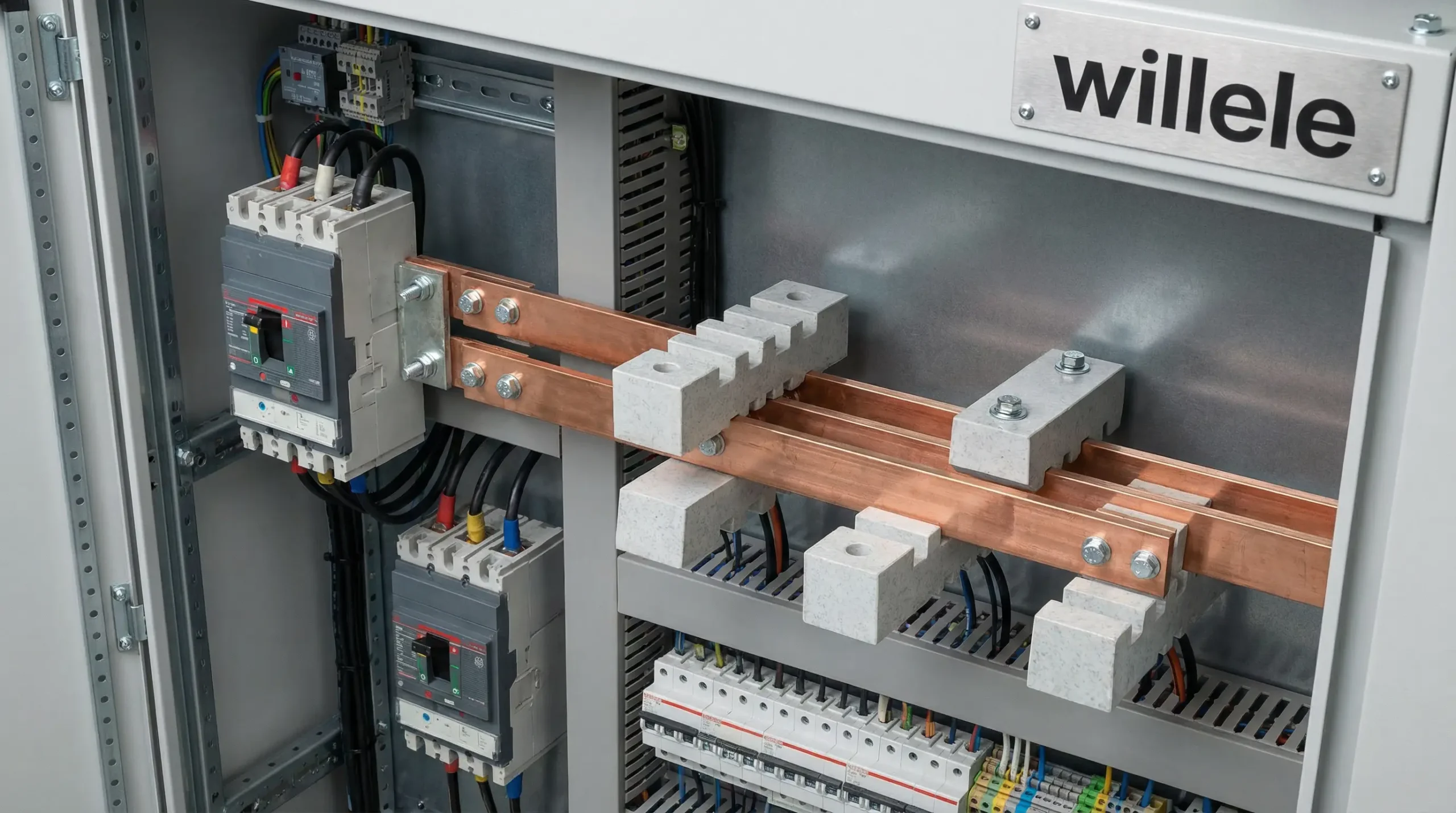
Electrical cabinet design requires meticulous attention to component placement, particularly when configuring low voltage busbar systems. Proper busbar insulator placement is critical for ensuring electrical safety, operational efficiency, and long-term reliability in industrial power distribution applications. As electrical systems become increasingly complex and space-constrained, understanding the principles of optimal insulator positioning can significantly impact cabinet performance, maintenance accessibility, and overall system longevity.
This comprehensive guide explores best practices for busbar insulator placement in electrical cabinet design, covering material selection, spacing requirements, thermal management considerations, and compliance with international standards. Whether you’re designing switchgear, motor control centers, or distribution panels, these insights will help you optimize your electrical cabinet design for maximum safety and performance.
Understanding Busbar Insulators and Their Critical Role
What Are Busbar Insulators?
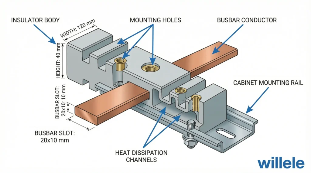
Busbar insulators serve as mechanical support structures and electrical isolation components within low voltage electrical cabinets. These specialized components prevent electrical current from flowing between busbars and the cabinet’s grounded metallic enclosure while providing rigid mounting points for heavy copper or aluminum conductors. In modern electrical cabinet design, insulators must withstand mechanical stress, thermal cycling, and environmental conditions while maintaining consistent dielectric properties.
Key Functions in Electrical Systems
Busbar insulators perform several essential functions:
- Electrical Isolation: Maintaining proper clearance and creepage distances between live conductors and grounded surfaces
- Mechanical Support: Bearing the weight of busbars and withstanding electromagnetic forces during short-circuit conditions
- Thermal Management: Allowing heat dissipation while maintaining structural integrity at elevated temperatures
- Arc Resistance: Preventing tracking and carbonization under fault conditions
- Vibration Dampening: Reducing mechanical stress from electromagnetic forces and external vibrations
Material Composition and Properties
Modern busbar insulators utilize advanced composite materials engineered for electrical cabinet applications. Common materials include:
- DMC (Dough Molding Compound): Thermosetting polyester resin with excellent arc resistance
- BMC (Bulk Molding Compound): High-strength molded composites for demanding applications
- Epoxy Resins: Superior mechanical properties and dimensional stability
- Ceramic Materials: Traditional choice for high-temperature environments
- Thermoplastic Composites: Cost-effective solutions for standard applications
Design Considerations for Optimal Placement
Electrical Clearance Requirements
Proper electrical cabinet design mandates specific minimum clearances based on voltage levels and environmental conditions. For low voltage systems (up to 1000V AC / 1500V DC), the following guidelines apply:
| Voltage Rating | Minimum Air Clearance | Minimum Creepage Distance | Pollution Degree |
|---|---|---|---|
| 230V AC | 4 mm | 6.3 mm | 2 (Normal) |
| 400V AC | 5.5 mm | 8 mm | 2 (Normal) |
| 690V AC | 8 mm | 12.5 mm | 2 (Normal) |
| 1000V AC | 12 mm | 20 mm | 2 (Normal) |
| 1500V DC | 14 mm | 25 mm | 2 (Normal) |
These values increase proportionally in environments with higher pollution degrees (industrial settings with conductive dust, chemical vapors, or moisture).
Mechanical Load Distribution
Busbar systems experience significant mechanical forces during normal operation and fault conditions. Optimal insulator placement must account for:
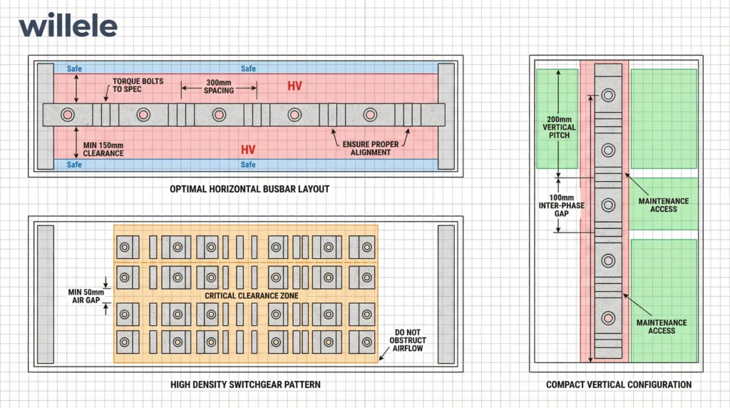
Static Loads: The weight of copper or aluminum busbars varies from 8.9 kg/m for copper to 2.7 kg/m for aluminum. Insulators should be spaced to prevent excessive bending stress, typically at 300-500mm intervals for horizontal runs.
Dynamic Loads: Short-circuit electromagnetic forces can reach 100-200 kN/m for high-current applications. Critical placement zones include:
- Phase-to-phase crossover points
- Incoming and outgoing connection points
- Sharp bend locations
- Junction boxes and tap-off points
Thermal Considerations
Heat generation in busbar systems affects insulator placement decisions. Electrical cabinet design must incorporate adequate spacing for:
- Natural convection airflow paths
- Heat sink mounting accessibility
- Thermal expansion allowances (copper expands 16.5 μm/m/°C)
- Hot spot monitoring equipment
Recommended practices include maintaining 30-50mm minimum spacing between parallel busbars and ensuring insulators have temperature ratings 20-30°C above expected operating temperatures.
Material Selection for Busbar Insulator Applications
Comparative Analysis of Insulator Materials
| Material Type | Temperature Rating | Arc Resistance | Mechanical Strength | Cost Index | Best Application |
|---|---|---|---|---|---|
| DMC Composite | 130-155°C | Excellent | High | 1.0x | General purpose, high-current |
| BMC Composite | 140-180°C | Excellent | Very High | 1.3x | Heavy-duty, industrial |
| Epoxy Resin | 130-155°C | Very Good | High | 1.2x | Precision applications |
| Ceramic | 200-400°C | Outstanding | Moderate | 1.8x | High-temperature zones |
| Thermoplastic | 85-120°C | Good | Moderate | 0.7x | Low-voltage, light-duty |
Heat Shrink Tube Integration
Modern electrical cabinet design increasingly incorporates heat shrink tube technology for enhanced insulation and environmental protection. Willele Electric specializes in manufacturing heat shrink tubes that complement busbar insulator systems through:
Primary Applications:
- Busbar connection point sealing
- Phase identification color-coding
- Additional insulation layers at termination points
- Moisture and contamination barriers
- Mechanical protection for exposed conductors
Material Compatibility: Heat shrink tubes must be selected based on:
- Operating temperature range (typically 125°C for low voltage applications)
- Shrink ratio (2:1 or 3:1 for irregular shapes)
- Dielectric strength (minimum 15 kV/mm)
- Chemical resistance to oils, solvents, and cleaning agents
- UV stability for outdoor or window-exposed cabinets
Selection Criteria Matrix
When designing electrical cabinets, use these criteria to select appropriate insulators:
| Selection Factor | Priority Level | Key Considerations |
|---|---|---|
| Voltage Rating | Critical | 1.5x safety factor above nominal voltage |
| Current Rating | Critical | Thermal rise ≤ 50K at rated current |
| Short-Circuit Withstand | High | Verified by testing per IEC 61439 |
| Environmental Rating | High | IP rating, corrosion resistance, humidity |
| Physical Dimensions | Medium | Cabinet space optimization |
| Mounting Method | Medium | Ease of installation and maintenance |
| Cost-Performance Ratio | Medium | Life-cycle cost analysis |
Installation Best Practices
Pre-Installation Planning
Successful electrical cabinet design begins with comprehensive planning:
- Load Calculation: Determine maximum continuous current and peak short-circuit levels
- Thermal Mapping: Identify heat concentration zones using thermal simulation software
- Accessibility Analysis: Ensure maintenance personnel can reach all connection points
- Future Expansion: Allocate 20-30% spare capacity for system growth
- Cable Routing: Plan conduit and wire ways to avoid crossing busbar zones
Mounting Techniques and Sequences
Standard Mounting Procedure:
- Clean mounting surfaces thoroughly, removing paint, oil, or debris
- Apply conductive grease to all metal-to-metal contact surfaces
- Position insulators using alignment fixtures or laser guides
- Torque mounting hardware to manufacturer specifications (typically 8-12 Nm for M6 fasteners)
- Install busbars with thermal expansion allowances (2-3mm per meter)
- Apply heat shrink tubes at connection points before final tightening
- Verify clearances with calibrated spacing gauges
- Document as-built dimensions and torque values
Spacing Configuration Guidelines
| Configuration Type | Horizontal Spacing | Vertical Spacing | Phase-to-Ground | Notes |
|---|---|---|---|---|
| Single-Phase System | 30-40 mm | 40-50 mm | 20-30 mm | Minimum for ≤63A |
| Three-Phase Delta | 40-60 mm | 50-70 mm | 25-40 mm | Standard industrial |
| Three-Phase Wye | 40-60 mm | 50-70 mm | 30-45 mm | With neutral bar |
| High-Current (>630A) | 60-100 mm | 80-120 mm | 40-60 mm | Enhanced cooling |
| Double-Deck System | 50-80 mm | 150-200 mm | 30-50 mm | Vertical separation |
Safety and Compliance Standards
International Standards Framework
Electrical cabinet design must comply with multiple overlapping standards:
IEC 61439 Series: Low-voltage switchgear and controlgear assemblies
- Part 1: General rules for type-tested and partially type-tested assemblies
- Part 2: Power switchgear and controlgear assemblies (PSC)
- Part 3: Distribution boards intended for operation by ordinary persons (DBO)
IEC 60947: Low-voltage switchgear and controlgear
- Specifications for insulating materials and clearances
UL 891: Dead-Front Switchboards (North American markets)
EN 60204-1: Safety of machinery – Electrical equipment of machines
Testing and Verification Requirements
Busbar insulator installations require verification through:
Visual Inspection:
- Clearance measurements at all critical points
- Proper torque application on all fasteners
- Heat shrink tube coverage and seal integrity
- Phase color-coding accuracy
- Label placement and legibility
Electrical Testing:
- Insulation resistance testing (minimum 1000V DC for low voltage systems)
- Dielectric strength verification at 2x rated voltage + 1000V
- Continuity verification of protective conductors
- Phase rotation confirmation
- Ground fault impedance measurement
Thermal Testing:
- Temperature rise testing at rated current (typically 24-hour duration)
- Hot spot identification using thermal imaging
- Verification that temperature rise ≤ 50K for busbars, 40K for connections
Environmental Protection Ratings
| IP Rating | Protection Level | Typical Applications | Cabinet Design Impact |
|---|---|---|---|
| IP20 | Basic touch protection | Indoor, clean environments | Standard insulator spacing |
| IP31 | Drip-proof | Indoor, slight moisture | Sealed bushings required |
| IP42 | Dust and drip protected | Light industrial | Gasketed enclosures |
| IP54 | Dust-tight, splash-proof | Outdoor, industrial | Enhanced sealing systems |
| IP65 | Dust-tight, water jet proof | Harsh environments | Specialized insulators, sealed |
Advanced Design Optimization Techniques
Computational Modeling Approaches
Modern electrical cabinet design leverages simulation tools for optimization:
Finite Element Analysis (FEA): Models electromagnetic forces during fault conditions to optimize insulator placement and structural reinforcement requirements.
Computational Fluid Dynamics (CFD): Simulates thermal performance, identifying optimal insulator positioning for natural or forced convection cooling.
CAD Integration: 3D modeling tools enable clash detection, ensuring busbar paths don’t interfere with other cabinet components before physical installation.
Modular Design Strategies
Standardizing insulator placement patterns across cabinet families provides multiple benefits:
- Reduced design time through template reuse
- Simplified spare parts inventory management
- Easier technician training and maintenance procedures
- Scalability for system expansion
- Quality consistency across production runs
Life-Cycle Cost Considerations
| Cost Component | Initial Installation | 10-Year Operation | 20-Year Life-Cycle |
|---|---|---|---|
| Premium Insulators | 1.3x | 1.1x | 1.0x |
| Standard Insulators | 1.0x | 1.2x | 1.4x |
| Economy Insulators | 0.7x | 1.5x | 2.0x |
Analysis: While premium insulators have higher initial costs, their superior thermal performance, reliability, and longer service life result in lower total cost of ownership. Factor in reduced maintenance, fewer unplanned shutdowns, and extended replacement intervals.
FAQ Section
What is the minimum spacing required between busbars in a 400V electrical cabinet?
For standard 400V three-phase systems in normal industrial environments (Pollution Degree 2), minimum phase-to-phase spacing should be 40-60mm, with at least 25-40mm clearance to grounded surfaces. These values may increase for harsh environments or higher fault current ratings. Always consult IEC 61439 and local electrical codes for specific requirements.
How do I calculate the required number of insulators for my busbar system?
Calculate insulator quantity based on busbar span, material, and current rating. As a general rule, space insulators 300-500mm apart for horizontal copper busbars up to 100A. For higher currents, reduce spacing proportionally. Electromagnetic forces during fault conditions may require closer spacing—consult manufacturer load tables or perform FEA analysis for currents exceeding 400A.
Can heat shrink tubes replace traditional busbar insulation?
Heat shrink tubes complement but don’t replace structural busbar insulators. While heat shrink tubes provide excellent electrical insulation and environmental protection at connection points and exposed conductor sections, rigid insulators are essential for mechanical support and maintaining proper clearances. Willele Electric recommends using both technologies together for optimal performance.
What temperature rating should busbar insulators have?
Select insulators with temperature ratings at least 20-30°C above expected operating conditions. For typical low voltage applications, insulators rated 130-155°C are appropriate. High-current systems (>630A) or cabinets in hot environments may require 155-180°C rated materials. Always verify that temperature rise testing confirms compliance with rated specifications.
How often should busbar insulator condition be inspected?
Implement a tiered inspection schedule: visual checks during routine maintenance (quarterly or semi-annually), detailed inspections including torque verification annually, and comprehensive testing (insulation resistance, thermal imaging) every 3-5 years. Critical installations or harsh environments may warrant more frequent inspection intervals.
What are the consequences of improper insulator placement in electrical cabinet design?
Inadequate insulator spacing or improper placement can lead to multiple failure modes: electrical flashover due to insufficient clearance, mechanical failure from excessive busbar deflection, premature aging from thermal stress, tracking and carbonization on insulator surfaces, and increased electromagnetic interference. Severe cases may result in arc flash incidents, equipment damage, or system downtime.
Conclusion
Optimal busbar insulator placement is fundamental to successful electrical cabinet design, directly impacting safety, reliability, and operational efficiency. By following established standards, selecting appropriate materials, maintaining proper clearances, and implementing rigorous testing protocols, engineers can design electrical cabinets that deliver decades of trouble-free service.
Key takeaways for electrical cabinet design excellence:
- Always exceed minimum clearance requirements by 20-30% safety margin
- Select insulator materials based on actual operating conditions, not just nominal ratings
- Integrate heat shrink tube technology for enhanced protection at critical connection points
- Perform comprehensive thermal analysis during the design phase
- Document all installation procedures and test results for future reference
- Plan for maintenance accessibility and future system expansion
Partner with Willele Electric for Superior Results
Willele Electric brings decades of specialized expertise in manufacturing high-performance electrical components, including industry-leading heat shrink tube solutions designed specifically for busbar applications. Our technical team provides comprehensive support throughout your electrical cabinet design process, from material selection to installation guidance and compliance verification.
Contact Willele Electric today to discuss your busbar insulator and heat shrink tube requirements. Our B2B solutions combine premium quality, competitive pricing, and responsive technical support to help you deliver electrical cabinet designs that exceed industry standards and customer expectations.
