Flame Retardant Heat Shrink Tubing in Power Distribution Systems
A short circuit inside a medium-voltage switchgear cabinet doesn’t just damage equipment — it can cascade into arc flash, fire propagation, and hours of unplanned downtime. In that moment, the difference between a contained incident and a catastrophic failure often comes down to a component most engineers never think twice about: the heat shrink tubing covering every termination, splice, and busbar joint.
Flame retardant heat shrink tubing serves as the last line of defense in power distribution systems. It insulates, seals, and — when things go wrong — refuses to become fuel. For electrical engineers, panel builders, and procurement specialists specifying components for switchgear, transformer connections, cable joints, and busbar systems, understanding how flame retardant heat shrink tubing performs under fault conditions is not a compliance checkbox. It is the foundation of system reliability.
What Is Flame Retardant Heat Shrink Tubing?
Flame retardant heat shrink tubing is a cross-linked polymer sleeve that shrinks tightly around cables, connectors, and busbars when heated. Unlike standard heat shrink tubing, the flame retardant variety is formulated with halogenated or halogen-free additives that interrupt the combustion cycle. When exposed to flame, the material self-extinguishes within a specified period — typically under 60 seconds — and resists propagating fire along cable runs.
The base polymer in most industrial-grade flame retardant heat shrink tubing is radiation cross-linked polyolefin. Cross-linking locks the polymer chains into a three-dimensional network, giving the material its “memory” — the ability to recover to a preset diameter when heated above its crystalline melting point. Flame retardant additives are compounded into the resin before extrusion, ensuring uniform fire performance throughout the wall thickness.
Common shrink ratios in power distribution applications include 2:1, 3:1, and 4:1. A higher ratio accommodates connectors and irregular shapes; a lower ratio suits uniform cable diameters. Wall thickness ranges from thin-wall (0.25–0.5 mm after recovery) for low-voltage control wiring to heavy-wall (1.5–4.5 mm) for medium-voltage cable joints operating up to 36 kV.
Why Flame Retardancy Matters in Power Distribution
Power distribution equipment operates under conditions that make fire propagation a genuine concern. Switchgear cabinets pack high-current conductors into confined spaces. A single loose connection can generate enough resistive heating to ignite surrounding materials. Cable trays in substations run for hundreds of meters through cable galleries where fire can travel unchecked.
Flame retardant heat shrink tubing addresses three distinct risks:
Internal arc containment. When an arc fault occurs inside switchgear, temperatures can exceed 20,000°C at the arc root. While no polymer survives direct arc exposure, flame retardant tubing on adjacent circuits prevents the fire from spreading to healthy cables. The material chars but does not sustain combustion.
Cable jacket fire propagation. A fire starting at one cable termination can follow the cable jacket like a fuse, spreading through penetrations into adjacent compartments. Flame retardant heat shrink tubing applied over terminations creates a firebreak — a section of material that will not propagate flame, stopping the fire at the source.
Toxic smoke reduction in occupied spaces. In building distribution systems — hospitals, data centers, commercial high-rises — flame retardant formulations increasingly specify low-smoke, zero-halogen (LSZH) characteristics. Halogen-free flame retardant heat shrink tubing eliminates the release of hydrogen chloride gas during combustion, which corrodes equipment and poses inhalation hazards to personnel.
Standards That Define Performance
Not all flame retardant claims are equal. The standards landscape separates verified performance from marketing language. The table below maps the key standards engineers encounter when specifying flame retardant heat shrink tubing for power distribution applications.
| Standard | Test Method | Key Criteria | Typical Voltage Class |
|---|---|---|---|
| UL 224 (VW-1) | Vertical wire flame — 5×15-second flame applications | Self-extinguish within 60 s; no ignition of cotton indicator | Up to 600 V |
| UL 94 V-0 | Vertical burn on material specimen | Self-extinguish ≤10 s per application; no flaming drips | All classes |
| UL 94 V-1 | Vertical burn on material specimen | Self-extinguish ≤30 s; non-flaming drips only | All classes |
| IEC 60684-3 | Series-specific flame tests | Harmonized with national standards; specifies performance tiers | Up to 36 kV for relevant parts |
| AS23053 (SAE) | References ASTM D2671 / D8355 | Class-dependent criteria; stringent for aerospace/military | Varies by class |
| EN 45545-2 (Rail) | Oxygen index, smoke density, toxicity | R22/R23 hazard levels for rolling stock | Up to 3 kV typical |
For most low-voltage power distribution (up to 1 kV), UL 224 VW-1 and UL 94 V-0 are the workhorse certifications. Medium-voltage applications (1–36 kV) add requirements for partial discharge resistance, tracking resistance, and thicker walls that meet IEC 60684-3 performance tiers. Rail and transit power distribution invokes EN 45545-2, which mandates not just flame retardancy but also stringent limits on smoke density and gas toxicity.
Single-Wall vs. Adhesive-Lined: Matching Construction to the Environment
The choice between single-wall and adhesive-lined (dual-wall) flame retardant heat shrink tubing turns on moisture ingress and mechanical stress. The table below summarizes the decision logic.
| Property | Single-Wall Flame Retardant | Adhesive-Lined (Dual-Wall) Flame Retardant |
|---|---|---|
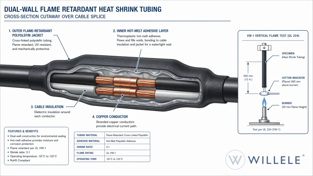
| Construction | One layer of cross-linked polyolefin with flame retardant additives | Outer flame retardant jacket + inner hot-melt adhesive layer |
| Typical shrink ratio | 2:1 to 3:1 | 3:1 to 4:1 |
| Moisture sealing | Minimal — relies on mechanical grip | Full environmental seal — adhesive flows into gaps |
| Strain relief | Moderate | High — adhesive bonds to cable jacket and connector |
| Dielectric strength | ≥20 kV/mm (thin-wall) | ≥15 kV/mm (adhesive layer reduces overall rating slightly) |
| Best for | Indoor switchgear, control panels, busbar identification | Outdoor terminations, underground joints, marine/offshore |
| Cost relative | Lower | 30–60% higher |
In practice, both types coexist in the same power distribution system. A typical low-voltage switchgear cabinet uses single-wall flame retardant tubing on control wiring and busbar sections, while cable entry glands and outdoor junction boxes demand adhesive-lined sleeves to prevent condensation and tracking.
Busbar Insulation: A Specialized Sub-Application
Busbars in power distribution panels present a unique challenge. They carry hundreds to thousands of amps, generate significant heat under load, and are often shaped in complex bends and transitions. Flame retardant heat shrink tubing for busbars must combine high dielectric strength with the mechanical toughness to survive installation over sharp copper edges.
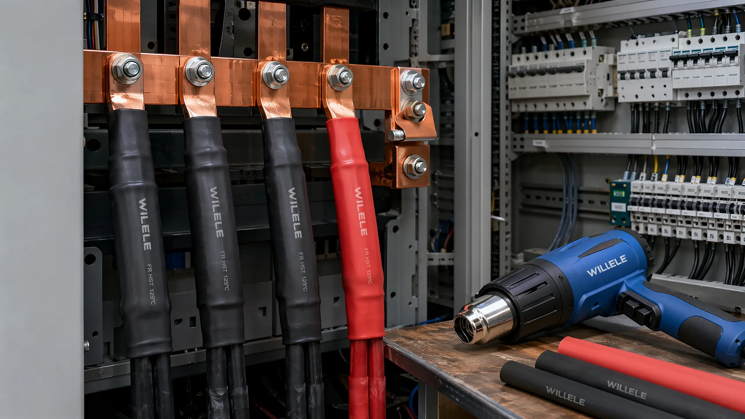
Busbar-rated flame retardant tubing is typically supplied in larger diameters (up to 200 mm flat width) with shrink ratios of 2:1 to 2.5:1. The material is formulated for continuous operating temperatures of 105°C to 125°C, with short-term excursion capability to 135°C. Color options — red, yellow, blue, black — enable phase identification that complies with IEC 60445 without the need for additional marking.
A key specification for busbar tubing is comparative tracking index (CTI). In polluted environments where conductive dust or salt spray accumulates on insulation surfaces, tracking can create a carbonized path that eventually causes flashover. Flame retardant busbar tubing with a CTI of 600 or higher provides an added margin against this failure mode.
Thermal Performance and Operating Limits
The flame retardant properties of heat shrink tubing must coexist with its electrical and mechanical performance across the full operating temperature range. The table below summarizes the thermal envelope for common material families used in power distribution.
| Material Family | Continuous Temp. Range | Shrink Temperature | UL 94 Rating (Typ.) | Key Application |
|---|---|---|---|---|
| Polyolefin (standard FR) | −55°C to +125°C | 90–120°C | VW-1 / V-0 | LV switchgear, control panels |
| Polyolefin (adhesive-lined) | −55°C to +110°C | 110–135°C | VW-1 / V-0 | Outdoor cable joints, underground |
| Fluoroelastomer (Viton®-type) | −55°C to +200°C | 150–175°C | V-0 | High-temp transformer leads |
| PVDF (Kynar®-type) | −55°C to +175°C | 150–175°C | V-0 | Chemical-resistant, semi-rigid |
| Silicone elastomer | −75°C to +200°C | 120–150°C | HB to V-1 | Extreme cold; limited FR performance |
Note that not all high-temperature materials carry strong flame retardant ratings. Silicone tubing, for example, offers outstanding flexibility and temperature range but generally achieves only UL 94 HB (horizontal burn), making it unsuitable for enclosed power distribution where V-0 is required. Fluoroelastomers and PVDF deliver both high-temperature capability and inherent flame resistance due to their halogen content.
Procurement Considerations for B2B Buyers
For procurement professionals sourcing flame retardant heat shrink tubing at scale, the decision extends beyond technical specifications into total cost of ownership and supply chain reliability. Several factors deserve attention before a purchase order is issued.
Batch-to-batch consistency. Flame retardant performance depends on precise additive loading. A supplier that cannot provide certificates of conformance (COC) with lot-level traceability introduces risk into every panel and cable joint shipped to end customers. Request the UL Yellow Card or equivalent third-party certification file for each SKU, not just a representative sample.
Dimensional recovery tolerance. The recovered wall thickness and inside diameter determine dielectric performance. Specifications such as AS23053 define recovery tolerances; verify that the supplier’s production records demonstrate statistical process control at or above these requirements. A tube that recovers 10% below nominal wall thickness may still pass visual inspection but fail a hipot test after thermal cycling.
Cut-length and spooling options. Power distribution work often demands specific cut lengths — 1.22 m sticks for busbar sections, continuous spools for harness shops. Confirm minimum order quantities (MOQs) and packaging options before committing to a product line. Some manufacturers offer custom cut-length services that reduce on-site waste and labor.
Cross-brand compatibility. In retrofit and maintenance scenarios, the replacement tubing must match the performance of the original without requiring requalification of the entire assembly. A manufacturer that provides cross-reference data against major industry part numbers — TE/Raychem, Sumitomo, DSG-Canusa — simplifies procurement and reduces lead time risk.
Willele Flame Retardant Heat Shrink Tubing
Willele manufactures flame retardant heat shrink tubing engineered specifically for power distribution applications. With over 18 years of experience in electrical insulation components and electron beam cross-linking technology in-house, Willele controls the full production chain — from resin compounding through extrusion, irradiation, expansion, and final inspection.
The product range covers the full spectrum of power distribution requirements. Single-wall polyolefin tubing is available in 2:1 and 3:1 shrink ratios, certified to UL 224 VW-1 and UL 94 V-0, with operating temperatures from −55°C to +125°C. Adhesive-lined dual-wall tubing in 3:1 and 4:1 ratios provides environmental sealing for outdoor and underground applications. Busbar-specific formulations deliver the dielectric strength and mechanical toughness required for high-current installations up to 36 kV.
Every production batch undergoes a three-stage quality control process — incoming resin inspection, in-process dimensional and flame testing, and outgoing verification against the relevant standard for the product family. Certificates of conformance, RoHS and REACH statements, and full 2D/3D drawings ship with every order.
For B2B buyers, Willele offers tiered pricing with framework agreements, consolidated shipments across multiple product families (heat shrink tubing, terminal blocks, busbar insulators, cable accessories), and engineering support including BOM matching and cross-reference against competitor part numbers. Standard SKUs ship within 7–15 days from safety stock; partial shipments and milestone-based delivery schedules accommodate project-driven procurement.
Frequently Asked Questions
What is the difference between flame retardant and flame resistant heat shrink tubing?
Flame retardant materials are formulated to slow ignition and self-extinguish once the flame source is removed. Flame resistant materials — a term more commonly applied to textiles and personal protective equipment — are designed to resist ignition entirely under brief flame exposure. For heat shrink tubing in power distribution, the relevant term is flame retardant, governed by standards such as UL 94 and UL 224 VW-1.
Which UL 94 rating should I specify for enclosed switchgear?
UL 94 V-0 is the recommended minimum for any tubing installed inside an enclosed power distribution assembly. Unlike V-1 or V-2, the V-0 rating prohibits flaming drips and requires self-extinguishing within 10 seconds of each flame application. In a densely packed switchgear cabinet, a flaming drip from V-2-rated tubing on an upper terminal block can ignite components below, defeating the purpose of flame retardant protection.
Can flame retardant heat shrink tubing be used outdoors?
Yes, provided the construction matches the environment. Adhesive-lined dual-wall flame retardant tubing creates a moisture-proof seal that prevents water ingress at cable joints and terminations. For UV exposure, confirm that the formulation includes carbon black or UV stabilizers. Standard colored tubing without UV protection will degrade within 12–24 months of direct sunlight exposure.
What voltage classes does flame retardant heat shrink tubing support?
Thin-wall tubing (0.25–0.5 mm recovered) is typically rated to 600 V. Medium-wall tubing covers 1 kV to 15 kV. Heavy-wall tubing, with recovered wall thickness of 1.5–4.5 mm, handles 15 kV to 36 kV applications. Always verify that the specific product carries the appropriate voltage rating for your system — wall thickness alone is not sufficient; the material’s dielectric strength and partial discharge performance must be certified.
Is halogen-free flame retardant tubing always the better choice?
Not necessarily. Halogen-free formulations (typically using metal hydrate fillers such as aluminum trihydroxide or magnesium hydroxide) eliminate toxic and corrosive gas emissions during combustion, making them essential for enclosed occupied spaces, tunnels, and rail applications governed by EN 45545-2. However, halogen-free flame retardant tubing generally has lower mechanical strength and higher water absorption than halogenated alternatives. For outdoor cable joints or high-mechanical-stress applications, a halogenated flame retardant formulation with proven sealing performance may be the safer overall choice.
How do I verify that the tubing I receive actually meets the flame retardant specification?
Request three documents from your supplier: the UL Yellow Card or equivalent third-party certification showing the exact SKU and rating, a lot-specific certificate of conformance verifying that the shipped batch was produced under the certified formulation, and — for critical applications — a sample test report from the supplier’s outgoing QC showing actual flame test results for that batch. A datasheet alone is not sufficient verification.
