
How to Test Low Voltage Busbar Insulator Performance Before Installation

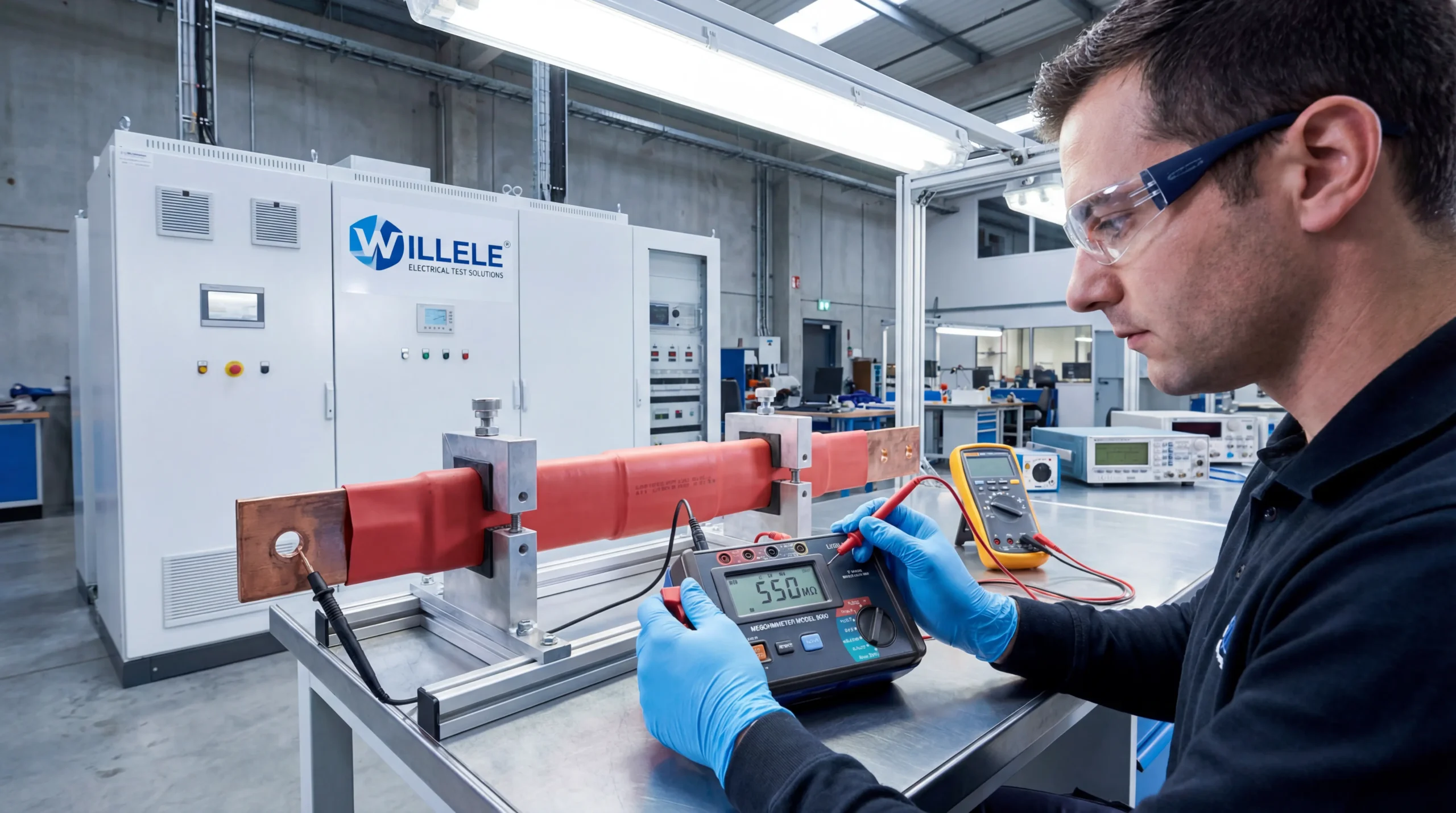
Ensuring the reliability of low voltage busbar insulators before installation is critical for electrical system safety and longevity. Proper pre-installation testing prevents costly failures, reduces downtime, and protects personnel from electrical hazards. This comprehensive guide outlines industry-standard testing procedures specifically designed for low voltage busbar systems using heat shrink insulation technology.
Understanding Low Voltage Busbar Insulator Requirements
Low voltage busbar insulators serve as the primary barrier between energized conductors and grounded surfaces in electrical distribution systems. These insulators, particularly heat shrink tubes manufactured for electrical applications, must meet stringent performance criteria before deployment. The insulation system protects against electrical breakdown, environmental degradation, and mechanical stress throughout the busbar’s operational lifetime.
Heat shrink tube insulators offer distinct advantages in busbar applications: they conform precisely to conductor geometry, eliminate air pockets that could cause partial discharge, and provide consistent dielectric strength across the entire surface. However, these benefits only materialize when the insulation material passes rigorous pre-installation testing protocols.
Essential Testing Equipment and Tools
Before beginning any testing procedure, assembling the correct measurement instruments ensures accurate results and compliance with international standards. The following equipment constitutes the minimum requirement for comprehensive busbar insulator testing:
| Equipment | Purpose | Specification Range | Accuracy Required |
|---|---|---|---|
| Megohmmeter (Insulation Tester) | Measures insulation resistance | 500V – 2500V DC | ±5% of reading |
| High Voltage Test Set | Performs dielectric withstand testing | 0-5 kV AC/DC | ±3% of output |
| Partial Discharge Detector | Identifies insulation defects | 5-50,000 pC sensitivity | <5 pC noise level |
| Digital Multimeter | Verifies continuity and resistance | 0.1Ω – 100MΩ | ±0.5% basic accuracy |
| Microhmmeter | Tests conductor resistance | 0.1μΩ – 2000Ω | ±0.25% of reading |
| Thermal Imaging Camera | Detects hot spots and defects | -20°C to 350°C | ±2°C or ±2% |
| Vernier Caliper | Measures insulation thickness | 0-150mm | ±0.02mm |
| Surface Contamination Tester | Assesses cleanliness | 0-999 μS | ±10% |
Each instrument must carry valid calibration certificates traceable to national standards. Calibration intervals should not exceed 12 months for critical measurement devices, ensuring test result reliability and regulatory compliance.
Pre-Test Visual Inspection Protocol
Visual examination represents the first line of defense against defective insulation. This non-destructive evaluation identifies obvious manufacturing flaws, shipping damage, or contamination that could compromise electrical performance. Conduct visual inspection under adequate lighting conditions, preferably 500-1000 lux illumination, using magnification tools for detailed examination.
Critical inspection checkpoints include:
The insulation surface must exhibit uniform color and texture without discoloration, chalking, or glossy patches indicating material degradation. Heat shrink tubes should show complete shrinkage with no bridging, wrinkling, or incomplete adhesion to the conductor surface. Any visible air pockets between the insulator and busbar create potential sites for partial discharge and eventual insulation failure.
Examine all edges and termination points where insulation meets connectors or joints. These high-stress areas require particular attention as they experience concentrated electrical field stress. The insulation should extend beyond the conductor edge by the manufacturer’s specified distance, typically 10-25mm for low voltage applications, providing adequate creepage and clearance distances.
Check for mechanical damage including cuts, abrasions, punctures, or compression marks that penetrate beyond the surface layer. Even minor surface damage can propagate under electrical stress, leading to premature failure. Foreign material contamination such as metal particles, dust, moisture, or chemical residues must be completely removed before proceeding with electrical testing.
Dimensional Verification and Thickness Measurement
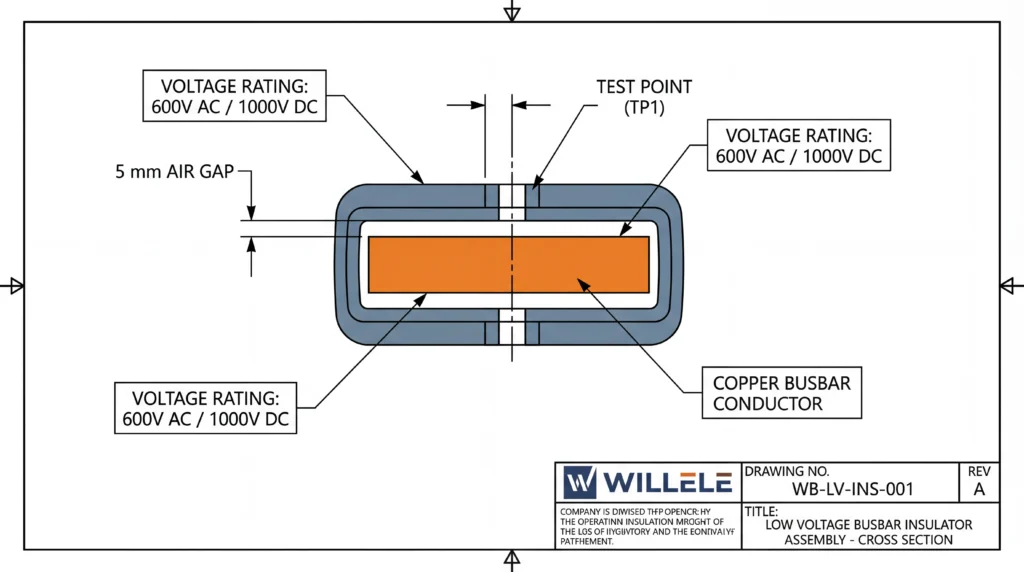
Accurate dimensional verification ensures the insulation system meets design specifications and provides adequate dielectric strength. Insufficient insulation thickness represents one of the most common causes of premature electrical failure in busbar systems.
Measure insulation wall thickness at multiple points around the conductor circumference using a calibrated vernier caliper or ultrasonic thickness gauge. For heat shrink tubes, take measurements at minimum intervals of 100mm along the busbar length, recording both minimum and maximum values. The thickness should remain within the manufacturer’s specified tolerance range, typically ±10% of nominal dimension.
Standard thickness requirements by voltage class:
| Voltage Rating | Minimum Insulation Thickness | Recommended Thickness | Maximum Thickness |
|---|---|---|---|
| Up to 300V | 0.8mm | 1.0-1.5mm | 2.5mm |
| 301-600V | 1.2mm | 1.5-2.0mm | 3.0mm |
| 601-1000V | 1.8mm | 2.0-3.0mm | 4.0mm |
Verify that the insulation extends beyond conductor edges with adequate overhang. This extension prevents electric field concentration at busbar terminations. Measure the creepage distance along the insulation surface between live parts and ground, ensuring compliance with IEC 61439 standards which specify minimum creepage distances based on pollution degree and voltage level.
Insulation Resistance Testing Procedure
Insulation resistance testing forms the cornerstone of pre-installation verification, providing quantitative assessment of the insulator’s ability to prevent current leakage. This test applies DC voltage across the insulation while measuring the resulting leakage current, expressed as resistance in megohms (MΩ) or gigohms (GΩ).
Step-by-step testing methodology:
Begin by ensuring the busbar conductor is completely disconnected from all electrical sources and grounded equipment. Clean the insulation surface with isopropyl alcohol to remove any surface contamination that could affect measurements. Allow the insulation to dry completely, as moisture significantly reduces apparent insulation resistance.
Connect the megohmmeter’s positive terminal to the busbar conductor and the negative terminal to a grounded reference point or metallic plate positioned against the insulation surface. For heat shrink tube testing, wrap aluminum foil around the insulation exterior to provide uniform contact, then connect the ground lead to this foil layer.
Select the appropriate test voltage based on the busbar’s rated operating voltage. Industry standards recommend applying test voltage at twice the rated voltage plus 1000V for equipment rated above 1000V, or 1000V for equipment rated below 1000V. For low voltage busbars (below 1000V), typical test voltages range from 500V to 1000V DC.
Apply the test voltage for a minimum duration of 60 seconds, allowing sufficient time for polarization currents to decay and obtain a stable reading. Record the insulation resistance value at 60 seconds. Quality heat shrink insulation should demonstrate resistance values exceeding 1000 MΩ at rated voltage, with many premium materials achieving 10,000 MΩ or higher.
Acceptance criteria for insulation resistance:
| Test Voltage | Minimum Acceptable Resistance | Good Quality Range | Excellent Performance |
|---|---|---|---|
| 500V DC | 100 MΩ | 500-1000 MΩ | >2000 MΩ |
| 1000V DC | 500 MΩ | 1000-5000 MΩ | >10,000 MΩ |
| 2500V DC | 1000 MΩ | 5000-10,000 MΩ | >50,000 MΩ |
Perform the polarization index (PI) test by taking resistance readings at both 1 minute and 10 minutes under continuous voltage application. Calculate the PI ratio by dividing the 10-minute reading by the 1-minute reading. A PI value above 2.0 indicates good insulation condition, while values below 1.5 suggest moisture contamination or insulation degradation requiring further investigation.
Dielectric Withstand (Hi-Pot) Testing
Dielectric withstand testing, commonly called hi-pot testing, verifies the insulation’s ability to withstand overvoltage conditions without breakdown. This test applies voltage significantly higher than normal operating levels to ensure adequate safety margin and identify weak points in the insulation system.
Configure the test setup with the busbar conductor connected to the high voltage output terminal and the ground terminal connected to the insulation’s outer surface through aluminum foil wrapping or a grounded metallic enclosure. Set the current trip threshold to 1-10 mA depending on the insulation surface area and test voltage level.
For AC dielectric testing, apply voltage at twice the rated voltage plus 1000V for one minute. For DC testing, apply 1.7 times the AC test voltage value. Increase the voltage gradually from zero to the test level over 10-15 seconds to avoid sudden stress on the insulation. Maintain the full test voltage for 60 seconds while monitoring for excessive leakage current or breakdown.
Recommended dielectric test voltages:
| Rated Voltage | AC Test Voltage (60 Hz) | DC Test Voltage | Test Duration |
|---|---|---|---|
| 300V | 1500V | 2550V | 60 seconds |
| 600V | 2200V | 3740V | 60 seconds |
| 1000V | 3000V | 5100V | 60 seconds |
Successful completion requires the insulation to withstand the full test voltage without breakdown, flashover, or leakage current exceeding the trip threshold. Any sudden current increase, audible discharge, or visible arcing indicates insulation failure requiring rejection of the component.
Partial Discharge Detection and Analysis
Partial discharge (PD) testing identifies microscopic defects within the insulation structure that may not cause immediate failure but will degrade over time, leading to premature breakdown. This advanced diagnostic technique detects electrical discharges occurring in voids, cracks, or at interfaces within the insulation system.
Connect PD detection sensors to the busbar system using capacitive coupling or high-frequency current transformers. Apply voltage gradually from zero to 1.2 times the rated voltage while monitoring for discharge activity. Modern PD detectors display discharge magnitude in picocoulombs (pC) and phase-resolved patterns that help identify defect types.
Quality heat shrink insulation should exhibit PD inception voltage above 1.5 times the rated operating voltage, with discharge magnitudes below 10 pC at rated voltage. Higher discharge levels or PD activity beginning near rated voltage indicate defects such as air pockets, contamination, or incomplete shrinkage requiring corrective action.
Partial discharge severity classification:
| PD Magnitude | Condition Assessment | Recommended Action |
|---|---|---|
| <5 pC | Excellent – No defects detected | Approve for installation |
| 5-10 pC | Good – Minor activity acceptable | Approve with monitoring |
| 10-50 pC | Fair – Investigation required | Detailed analysis needed |
| >50 pC | Poor – Significant defects present | Reject and replace |
Surface Resistance and Contamination Testing
Surface contamination significantly impacts insulation performance by creating conductive paths that facilitate tracking and flashover. Testing surface resistance quantifies the insulation’s outer layer conductivity, identifying contamination from manufacturing residues, handling, or environmental exposure.
Clean a representative section of the insulation surface with deionized water and allow it to dry completely. Place two parallel electrodes 100mm apart on the insulation surface and apply 500V DC between them using a megohmmeter. Measure the surface resistance after 60 seconds of voltage application.
Clean, dry heat shrink insulation should demonstrate surface resistance exceeding 1000 MΩ. Values below 100 MΩ indicate contamination requiring thorough cleaning before installation. Common contaminants include silicone residues, mold release agents, salt deposits, and industrial pollutants that accumulate during storage or handling.
Thermal Performance Verification
Heat shrink insulators must maintain electrical properties across their rated temperature range. Thermal testing verifies the material’s stability under temperature extremes encountered during normal operation and overload conditions.
Subject sample sections of the insulation to thermal cycling between -40°C and +105°C (or the manufacturer’s specified range) for minimum 10 cycles. After thermal conditioning, repeat insulation resistance and dielectric withstand tests to verify performance retention. Quality materials should show less than 20% reduction in insulation resistance after thermal cycling.
Use thermal imaging to inspect installed heat shrink tubes for uniform temperature distribution during current loading tests. Hot spots indicate poor contact, inadequate heat dissipation, or localized defects requiring investigation before final installation approval.
Documentation and Test Record Requirements
Comprehensive documentation ensures traceability and provides baseline data for future condition monitoring. Create detailed test records including:
Essential documentation elements:
- Busbar identification (serial number, project reference, location)
- Insulation material specifications (manufacturer, type, thickness, rating)
- Test equipment used (model, serial number, calibration date)
- Environmental conditions (temperature, humidity, date, time)
- Complete test results with pass/fail criteria
- Technician identification and certification level
- Photographic evidence of visual inspection findings
- Any deviations from standard procedures with justification
Maintain test records for the equipment’s operational lifetime, typically 20-30 years for electrical infrastructure. These records prove invaluable for warranty claims, failure analysis, and regulatory compliance verification.
Common Testing Pitfalls and How to Avoid Them
Even experienced technicians encounter challenges during pre-installation testing. Understanding common errors prevents false readings and ensures accurate assessment:
Surface moisture contamination represents the most frequent cause of artificially low insulation resistance readings. Always verify the insulation surface is completely dry before testing. Consider using a heat gun or allowing extended drying time in humid environments. Relative humidity above 80% requires special precautions including controlled environment testing or moisture correction factors.
Inadequate contact between test electrodes and insulation produces inconsistent results. When testing heat shrink tubes, aluminum foil wrapping ensures uniform contact across the entire surface. Ensure the foil extends over sufficient area without gaps or wrinkles that create air pockets.
Insufficient voltage application time yields unstable readings as polarization currents continue flowing. Always maintain test voltage for the full specified duration, typically 60 seconds minimum. For critical applications, extended testing to 10 minutes provides additional confidence through polarization index calculation.
Testing immediately after heat shrink application can produce misleading results as the material continues curing and outgassing. Allow minimum 24 hours after shrinking before conducting electrical tests, or follow the manufacturer’s recommended conditioning period.
Quality Assurance and Acceptance Standards
Establishing clear acceptance criteria ensures consistent quality and reduces disputes over component approval. Base acceptance standards on relevant industry codes including IEC 61439 for low voltage switchgear, IEEE 386 for separable insulated connectors, and manufacturer specifications.
Comprehensive acceptance checklist:
| Test Parameter | Acceptance Criteria | Rejection Criteria |
|---|---|---|
| Visual Inspection | No defects, uniform appearance | Visible damage, contamination, incomplete shrinkage |
| Insulation Thickness | Within ±10% of specification | Below minimum specified thickness |
| Insulation Resistance (1000V) | >1000 MΩ | <500 MΩ |
| Polarization Index | >2.0 | <1.5 |
| Dielectric Withstand | No breakdown or excessive leakage | Breakdown, flashover, or trip |
| Partial Discharge | <10 pC at rated voltage | >50 pC at rated voltage |
| Surface Resistance | >1000 MΩ | <100 MΩ |
Components meeting all acceptance criteria receive approval for installation. Marginal results require engineering evaluation to determine suitability for the specific application. Any component failing critical tests must be rejected and replaced to ensure system reliability and safety.
Frequently Asked Questions
Q: How often should busbar insulators be tested after installation?
A: While this article focuses on pre-installation testing, installed busbar insulators should undergo periodic testing every 3-5 years as part of preventive maintenance programs. More frequent testing may be required in harsh environments or critical applications. Annual visual inspections help identify developing issues before they cause failures.
Q: Can I use AC voltage instead of DC for insulation resistance testing?
A: DC voltage is strongly recommended for insulation resistance testing because it provides more stable readings and better sensitivity to insulation defects. AC testing introduces capacitive effects that can mask insulation problems. However, AC dielectric withstand testing is preferred over DC for final voltage withstand verification as it better simulates actual operating conditions.
Q: What is the minimum acceptable insulation resistance for low voltage busbars?
A: Industry standards typically require minimum insulation resistance of 1 MΩ per kilovolt of rated voltage, with an absolute minimum of 1 MΩ for any voltage level. However, quality heat shrink insulation should easily achieve 1000 MΩ or higher. Values below 100 MΩ indicate serious problems requiring investigation and likely component rejection.
Q: Do heat shrink tubes need special testing compared to other insulation types?
A: Heat shrink tubes require verification of complete shrinkage and adhesion to the conductor surface, which is unique to this technology. Visual inspection must confirm no bridging or air pockets exist. Otherwise, electrical testing procedures remain consistent with other insulation types, though heat shrink materials typically demonstrate superior performance in partial discharge and insulation resistance tests.
Q: Can I reuse busbar insulators that pass all pre-installation tests?
A: Reusing insulators is generally not recommended even if they pass testing. The installation process, particularly for heat shrink tubes, is permanent and cannot be reversed without damaging the insulation. Additionally, handling during removal introduces contamination and potential mechanical damage that compromises future performance. The cost savings rarely justify the increased failure risk.
