
Industrial Control Panel Applications for Low Voltage Busbar Insulators

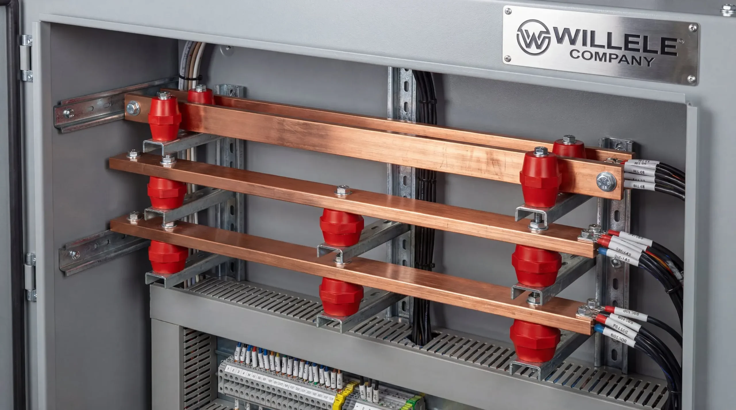
Low voltage busbar insulators serve as the backbone of electrical distribution systems within industrial control panels, providing critical electrical isolation and mechanical support for copper and aluminum busbars. As power distribution demands increase in manufacturing facilities, data centers, and industrial plants, understanding the applications, specifications, and selection criteria for these essential components becomes paramount for electrical engineers, panel builders, and maintenance professionals.
Understanding Low Voltage Busbar Insulators
Low voltage busbar insulators are specialized electrical components designed to support and electrically isolate busbars from the grounded enclosure and other conductive parts within switchgear assemblies. These insulators must withstand mechanical loads while maintaining dielectric integrity across a wide range of operating conditions, ensuring personnel safety and equipment reliability in industrial environments.
The fundamental purpose extends beyond simple mechanical support. These components create defined air gaps and creepage distances that prevent tracking, arcing, and insulation breakdown under normal operating voltages and transient overvoltage conditions. Modern insulators incorporate advanced polymer composites that offer superior performance compared to traditional porcelain alternatives, particularly in challenging industrial settings where contamination, humidity, and temperature fluctuations test electrical insulation systems.
Electrical Performance Specifications
Low voltage busbar insulators typically accommodate voltage ratings from 660V to 4500V, covering the requirements for most industrial control panels and distribution equipment. The insulation resistance specifications exceed 1500MΩ under standard test conditions, ensuring leakage current remains below 1mA even at elevated test voltages of 2000V. This level of insulation integrity proves essential in switchgear assemblies where parallel busbars may operate with minimal clearance distances—as narrow as 15mm—while maintaining full dielectric withstand capabilities.
Impulse withstand testing validates insulator performance under transient conditions, with standard products rated for 10kV impulse voltage using 1.2/50μs waveforms. Partial discharge testing at 1.5 times rated voltage ensures corona-free operation, with acceptable discharge levels below 5pC indicating high-quality manufacturing and material consistency. These electrical characteristics directly impact long-term reliability and maintenance intervals in continuous-duty industrial applications.
Mechanical Load Capabilities
The mechanical strength of busbar insulators determines their suitability for supporting substantial copper or aluminum conductors while withstanding electrodynamic forces during short-circuit events. Standard SM-76 type insulators demonstrate axial tensile strength ratings of 4000N and bending load capacity of 5000N, providing substantial safety margins for typical busbar weights and fault current stresses.
Dimensional stability under mechanical load ensures precise busbar alignment within ±0.5mm tolerances, critical for maintaining proper phase spacing and preventing mechanical interference with operating equipment. Threaded inserts—typically brass or stainless steel—provide secure mounting interfaces for M6 through M12 fasteners, accommodating various busbar configurations and connection requirements.
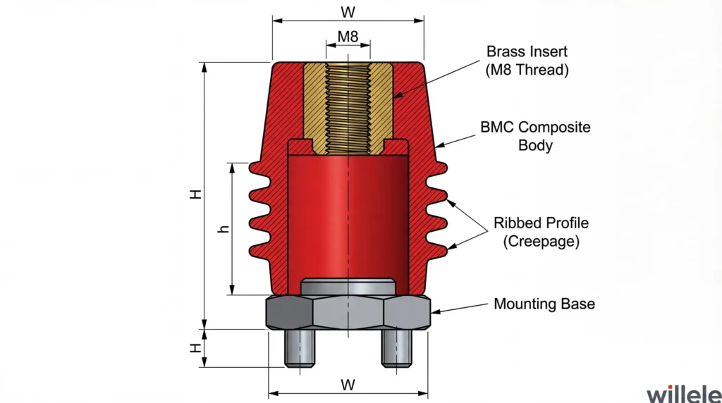
Figure 2: Technical cross-section view of BMC composite standoff insulator showing brass threaded insert, ribbed body profile for increased creepage distance, and hexagonal mounting base with integrated studs.
Material Technologies and Composition
The evolution of busbar insulator materials has significantly improved performance characteristics while reducing weight and installation complexity. Modern industrial applications predominantly utilize engineered polymer composites that combine excellent electrical properties with mechanical durability.
DMC/BMC Composite Materials
Bulk Molding Compound (BMC) and Dough Molding Compound (DMC) thermoset composites dominate the low voltage busbar insulator market due to their exceptional balance of properties. These materials incorporate unsaturated polyester resins reinforced with glass fibers and mineral fillers, creating components with high dielectric strength (typically 15-20 kV/mm), excellent dimensional stability, and resistance to thermal cycling.
The molding process enables complex geometries including ribbed profiles that increase creepage distances without increasing overall height. BMC materials demonstrate low water absorption rates below 0.15%, maintaining electrical integrity in humid environments common to industrial facilities. The UL 94 V-0 flammability rating ensures self-extinguishing characteristics, critical for fire safety in enclosed electrical equipment.
Epoxy Resin Systems
Epoxy-based insulators offer superior electrical properties and minimal moisture absorption, making them suitable for high-reliability applications and environments with significant condensation potential. The cross-linked polymer structure provides excellent tracking resistance and maintains dielectric strength over decades of service life. However, epoxy materials typically cost more than BMC alternatives and may degrade under prolonged ultraviolet exposure, limiting outdoor applications without protective coatings.
Ceramic and Porcelain
Traditional ceramic insulators retain specialized applications requiring exceptional compressive strength and thermal stability. Porcelain materials withstand extreme temperatures beyond 1000°C and resist surface tracking under severe contamination. These characteristics prove valuable in heavy industrial environments with conductive dust, chemical exposure, or extreme thermal conditions. However, ceramic’s brittleness requires careful handling and mounting to prevent mechanical damage during installation or seismic events.
Industrial Control Panel Applications
Industrial control panels integrate busbar insulators across numerous functional areas, each presenting unique requirements for electrical clearance, mechanical support, and environmental protection.
Main Power Distribution
Incoming power feeders and main bus systems within Motor Control Centers (MCCs) and Power Control Centers (PCCs) rely on high-strength insulators capable of supporting substantial conductor cross-sections. Three-phase busbar systems commonly employ insulator heights ranging from 25mm to 76mm, creating adequate phase-to-phase and phase-to-ground clearances while minimizing panel depth requirements. The modular nature of standoff insulators allows flexible busbar configurations including horizontal, vertical, and stacked arrangements optimized for specific panel layouts.
Branch Circuit Protection
Distribution sections feeding circuit breakers, fuses, and motor starters utilize smaller insulators sized for reduced conductor cross-sections while maintaining proper spacing from protective devices. The compact profiles of EL-series and similar insulators enable high-density layouts without compromising safety clearances or accessibility for maintenance operations.
Variable Frequency Drive Systems
VFD installations present unique challenges due to harmonic content and reflected wave phenomena that stress insulation systems. Busbar insulators in drive applications must withstand elevated voltage transients while maintaining low partial discharge characteristics. Proper insulator selection, combined with appropriate spacing and shielding practices, minimizes premature aging of insulation systems in variable speed drive installations.
DC Power Systems
Battery banks, UPS systems, and DC distribution panels utilize busbar insulators designed for continuous DC voltage stress without the self-healing characteristics present in AC applications. DC-rated insulators typically feature enhanced creepage distances and materials selected for resistance to electrolytic tracking under DC polarization.
Standards and Compliance Requirements
International standards govern busbar insulator design, testing, and application to ensure safety and interoperability across global markets.
IEC 61439 Series
The IEC 61439 standard for low-voltage switchgear and controlgear assemblies defines design verification requirements including dielectric properties, short-circuit withstand, and temperature rise limits. Insulators incorporated into IEC-compliant assemblies must demonstrate adequate performance under specified test conditions, including verification of clearances and creepage distances appropriate for the declared pollution degree and overvoltage category.
Insulation Coordination per IEC 60664-1
IEC 60664-1 establishes insulation coordination principles for equipment within low-voltage systems, specifying minimum clearances and creepage distances based on rated voltage, overvoltage category, and pollution degree. For systems rated 690V and below, standard installations require minimum air clearances of 10mm and creepage distances of 14mm in clean environments (Pollution Degree 2). Higher pollution degrees or system voltages approaching 1000V necessitate increased clearances to 18mm and creepage distances to 22mm or greater.
North American Standards
UL 891 governs switchboards in North American markets, while UL 508A applies to industrial control panels. These standards incorporate flammability requirements (UL 94 V-0 minimum for insulating materials), tracking resistance specifications, and mechanical integrity testing. CSA C22.2 No. 14 provides analogous Canadian requirements for industrial control equipment.
Material Comparison and Selection Guide
Selecting the appropriate busbar insulator material requires balancing electrical performance, mechanical requirements, environmental conditions, and cost considerations.
| Property | BMC/DMC Composite | Epoxy Resin | Porcelain/Ceramic |
|---|---|---|---|
| Dielectric Strength | 15-20 kV/mm | 20-30 kV/mm | 25-35 kV/mm |
| Water Absorption | <0.15% | <0.05% | <0.1% |
| Operating Temperature | -40°C to 130°C | -50°C to 155°C | -60°C to 1000°C |
| Impact Resistance | Excellent | Good | Poor |
| Weight | Light | Medium | Heavy |
| UV Resistance | Good (stabilized) | Poor (requires coating) | Excellent |
| Cost | Low | Medium | High |
| Tracking Resistance | Good | Excellent | Excellent |
| Flammability Rating | UL 94 V-0 | UL 94 V-0 | Non-combustible |
| Typical Applications | General industrial, MCCs | High-humidity, precision | Outdoor, extreme heat |
This comparison reveals BMC/DMC composites as the optimal choice for most indoor industrial control panel applications, offering the best combination of performance, durability, and value. Epoxy systems excel in specialized high-humidity or precision applications where maximum electrical performance justifies additional cost. Porcelain remains the solution for extreme temperature environments or severe contamination conditions where material stability under thermal stress outweighs handling and weight considerations.
Selection Criteria for Industrial Applications
Effective insulator selection involves systematic evaluation of electrical, mechanical, and environmental factors specific to each installation.
Voltage Rating Verification
The insulator voltage rating must equal or exceed the maximum system voltage, including consideration of temporary overvoltages and transient conditions. For three-phase systems, selection based on line-to-line voltage ensures adequate phase-to-phase insulation margins. DC applications require voltage ratings approximately 1.5 times higher than equivalent AC ratings due to the absence of zero-crossings that provide self-healing opportunities for minor insulation stress.
Mechanical Loading Analysis
Static mechanical loads include busbar weight, particularly for long horizontal spans where conductor mass creates bending moments at insulator mounting points. Dynamic loads during short-circuit events generate substantial electrodynamic forces—proportional to the square of fault current—requiring insulators with adequate tensile and cantilever strength margins. Safety factors of 2.0 or greater relative to calculated maximum loads ensure reliable performance under worst-case fault conditions.
Environmental Considerations
Operating temperature ranges must accommodate both ambient conditions and resistive heating from busbar current flow. Standard BMC insulators maintain structural integrity and electrical properties from -40°C to 130°C, covering most industrial environments. Extreme cold applications may require special low-temperature formulations to prevent embrittlement, while high-temperature zones near furnaces or engines may necessitate ceramic insulators or enhanced polymer grades.
Chemical exposure requires material compatibility assessment. Standard polyester-based BMC materials resist oils, greases, and common industrial solvents. Aggressive chemical environments—strong acids, bases, or chlorinated solvents—may require epoxy systems or specialized formulations with enhanced chemical resistance.
Installation Best Practices
Proper installation practices ensure insulator performance throughout the equipment service life while facilitating maintenance access and minimizing field failures.
Mounting and Torque Specifications
Insulator mounting bases require flat, clean surfaces capable of supporting mechanical loads without distortion. Threaded inserts accept mounting hardware with specified torque values—typically 4-8 Nm for M6 threads, 8-15 Nm for M8, and 15-25 Nm for M10—ensuring secure retention without cracking the composite body. Excessive torque compromises mechanical integrity and may create internal cracks that propagate under thermal cycling.
Busbar attachment to insulator top fittings requires compatible hardware and appropriate torque. Belleville washers or similar spring-type fasteners maintain consistent contact pressure through thermal expansion cycles, preventing loosening that could create hot spots or arcing surfaces.
Spacing and Layout Optimization
Optimal insulator placement balances electrical clearance requirements with space utilization efficiency. Standard practice spaces insulators at intervals preventing excessive busbar sag while maintaining phase spacing integrity. For horizontal busbars, spacing of 600-800mm between insulators typically provides adequate support for standard copper bar sizes without excessive material usage.
Phase-to-phase spacing must accommodate both steady-state voltage stress and transient overvoltages while allowing adequate clearance for tools and protective equipment during maintenance. Minimum spacing requirements increase with system voltage and pollution severity, with typical industrial installations using 25-50mm phase spacing for low voltage systems.
Frequently Asked Questions
What voltage range do low voltage busbar insulators cover?
Low voltage busbar insulators typically support voltage ratings from 660V to 4500V, accommodating the requirements for most industrial control panels, switchgear, and distribution equipment operating at standard low voltage levels.
How do I select the correct insulator height for my application?
Insulator height selection depends on required electrical clearances, busbar positioning, and panel space constraints. Standard heights range from 20mm for compact panels to 76mm for main distribution busbars requiring substantial spacing. Consult IEC 60664-1 or UL standards for minimum clearance requirements based on your system voltage and pollution degree.
Can BMC composite insulators be used outdoors?
Standard BMC insulators incorporate UV stabilizers suitable for outdoor applications, though extended UV exposure may cause gradual surface degradation. For critical outdoor installations or severe UV environments, specify UV-enhanced formulations or consider porcelain alternatives for maximum longevity.
What maintenance do busbar insulators require?
Insulators generally require minimal maintenance beyond periodic visual inspection for cracks, tracking marks, or contamination buildup. Clean contaminated surfaces using dry cloths or approved solvents—avoiding abrasive materials that damage surface finishes. Tighten mounting and busbar hardware during scheduled maintenance intervals to address thermal cycling effects.
How do short-circuit currents affect insulator selection?
Short-circuit events generate electrodynamic forces proportional to current squared, creating substantial mechanical stress on insulators. Select insulators with cantilever and tensile ratings exceeding calculated maximum fault forces by appropriate safety margins—typically 2.0 or greater—to ensure mechanical integrity under worst-case conditions.
