
Manufacturing Plant Electrical Systems: Busbar Insulator Solutions

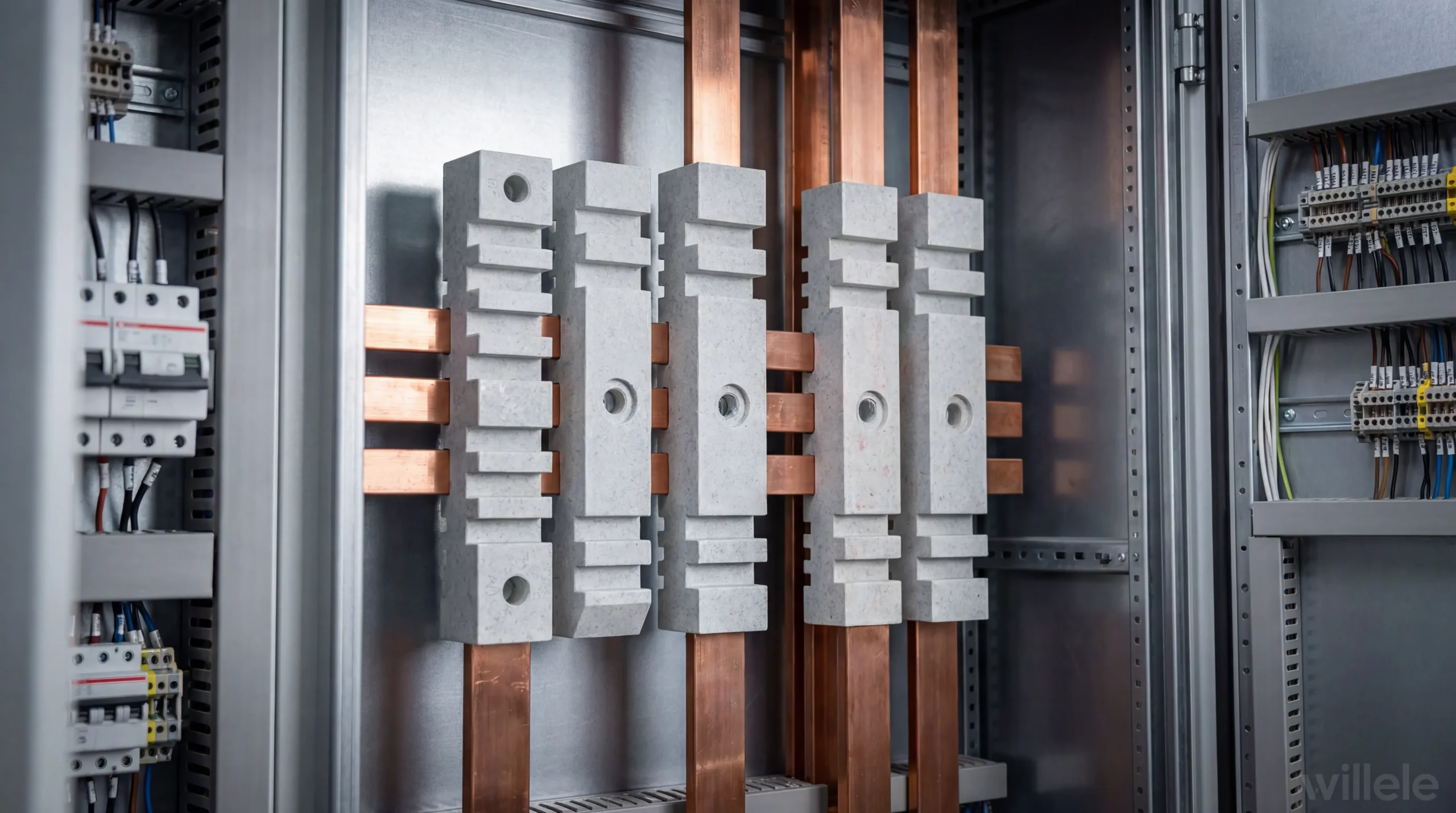
In modern manufacturing facilities, reliable electrical distribution systems form the backbone of operational efficiency. Among the critical components ensuring safe and continuous power flow, busbar insulators play an indispensable role. These specialized electrical components provide mechanical support and electrical isolation for busbars—the metal bars or strips that conduct electricity within switchboards, distribution boards, substations, and battery banks. For plant managers, electrical engineers, and procurement professionals seeking dependable solutions, understanding busbar insulator technology is essential for maintaining system integrity and preventing costly downtime.
Understanding Busbar Insulators in Industrial Applications
Busbar insulators serve a dual purpose in electrical systems: they physically support heavy busbar conductors while preventing electrical current from escaping to grounded enclosures or adjacent phases. In manufacturing environments where electrical loads can reach thousands of amperes, selecting appropriate insulator solutions becomes paramount for both safety and operational continuity.
The fundamental working principle relies on materials with high dielectric strength—typically ceramics, composites, or specialized polymers—that can withstand significant electrical stress without breakdown. These materials must simultaneously endure mechanical loads from the weight of busbars, thermal cycling from current fluctuations, and environmental factors including humidity, dust, and chemical exposure common in industrial settings.
Modern manufacturing plants demand insulators capable of operating across wide temperature ranges, often from -40°C to +120°C or higher. The insulators must maintain their electrical and mechanical properties despite thermal expansion cycles that occur daily in active facilities. Additionally, they must resist tracking—surface carbonization that creates conductive paths—and erosion from partial discharge activities that gradually degrade material integrity.
Critical Design Considerations for Manufacturing Plant Applications
Selecting busbar insulators requires careful evaluation of multiple electrical and mechanical parameters. The voltage rating must exceed the system’s maximum operating voltage with appropriate safety margins, typically 15-20% above nominal levels. More critically, the insulator’s creepage distance—the shortest path along the surface between conductive parts—must be sufficient for the installation environment’s pollution level. Industrial environments with conductive dust or moisture require significantly greater creepage distances than clean indoor installations.
Mechanical load capacity represents another crucial specification. Insulators must support not only the static weight of busbars but also dynamic forces from electromagnetic stresses during short-circuit events. These fault conditions can generate tremendous mechanical stress as parallel conductors experience strong magnetic repulsion. High-quality insulators incorporate safety factors of 3:1 or greater for normal operating loads, ensuring reliability even under abnormal system conditions.
The mounting configuration also influences selection decisions. Post insulators stand vertically from mounting surfaces, while support insulators accommodate horizontal busbar runs. Some applications require specialized designs including threaded inserts for direct conductor attachment or multi-tier configurations for phase segregation in compact switchgear assemblies.
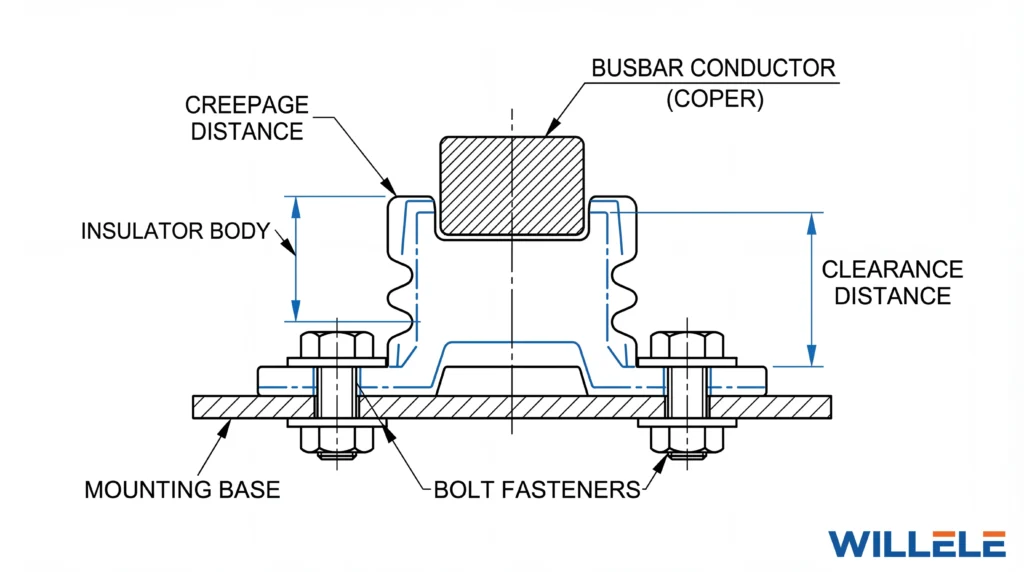
Technical schematic illustrating busbar insulator mounting configuration with critical dimensional parameters
Material Technologies and Performance Characteristics
Contemporary busbar insulators utilize several advanced material formulations, each offering distinct advantages for specific applications. Understanding these material properties enables informed selection aligned with operational requirements and environmental conditions.
Porcelain and Ceramic Insulators
Traditional porcelain remains prevalent for high-voltage outdoor installations due to excellent weather resistance and surface stability. Modern ceramic formulations incorporate alumina for enhanced mechanical strength, achieving tensile strengths exceeding 10,000 psi. These materials demonstrate exceptional resistance to surface arcing and maintain dielectric properties across decades of service. However, porcelain’s brittleness requires careful handling during installation and makes it susceptible to damage from mechanical impact or thermal shock.
Epoxy Resin Composites
Cast epoxy insulators dominate indoor medium-voltage applications, offering excellent dielectric properties combined with mechanical robustness. These materials permit complex geometries optimized for electric field distribution, reducing stress concentrations that initiate failure. Epoxy systems incorporate fillers such as silica or alumina trihydrate to enhance tracking resistance and thermal conductivity. The manufacturing process allows integration of metal inserts for threaded connections, simplifying assembly and improving reliability compared to post-mounted alternatives.
Polymer and Composite Insulators
Silicone rubber and other polymer formulations provide lightweight alternatives with superior contamination performance. The hydrophobic surface properties cause water to bead rather than form continuous films, maintaining high surface resistivity even in polluted environments. These materials resist vandalism and mechanical impact better than ceramics, making them suitable for exposed locations. However, polymer degradation from ultraviolet exposure and electrical stress requires careful material selection and may limit service life in certain applications.
Comparative Analysis of Busbar Insulator Technologies
The following comprehensive comparison evaluates leading busbar insulator technologies across parameters critical to manufacturing plant applications:
| Performance Parameter | Porcelain/Ceramic | Epoxy Resin Composite | Silicone Polymer |
|---|---|---|---|
| Dielectric Strength | 15-20 kV/mm | 12-18 kV/mm | 20-30 kV/mm |
| Mechanical Strength | High compressive, brittle | Excellent all-directional | Moderate, flexible |
| Temperature Range | -40°C to +150°C | -30°C to +120°C | -50°C to +150°C |
| Contamination Performance | Good (requires washing) | Excellent | Superior (hydrophobic) |
| Weight | Heavy (2.5-4× polymer) | Moderate | Light |
| Impact Resistance | Poor | Good | Excellent |
| UV Resistance | Excellent | Good | Moderate (stabilizers required) |
| Typical Service Life | 30+ years | 20-25 years | 15-20 years |
| Initial Cost | Moderate | Moderate-High | Low-Moderate |
| Maintenance Requirements | Periodic cleaning | Minimal | Minimal |
| Fire Resistance | Non-combustible | Self-extinguishing | Varies by formulation |
This comparison reveals that no single material dominates all applications. Epoxy resin composites offer the best balance for controlled indoor environments, while silicone polymers excel in contaminated or hard-to-access locations where maintenance is challenging. Porcelain maintains advantages for extreme temperature applications and installations where longevity outweighs initial cost considerations.
Integration with Heat Shrink Insulation Systems
For comprehensive busbar protection, insulators function alongside complementary insulation technologies—particularly heat shrink tubing systems. While insulators provide point support and phase separation, heat shrink tubing offers continuous insulation along conductor lengths, protecting against accidental contact and environmental contamination.
Quality heat shrink installations require careful surface preparation and controlled application. The tubing must be selected with appropriate shrink ratios and voltage ratings exceeding system requirements. Dual-wall adhesive-lined products provide superior moisture sealing for humid environments or outdoor installations. Color-coding options facilitate phase identification and safety compliance.
The combination of robust mechanical insulators and comprehensive heat shrink coverage creates redundant protection systems. Should one component degrade or sustain damage, the other maintains safety margins until maintenance intervention. This layered approach significantly reduces the risk of catastrophic failures that could damage equipment or endanger personnel.
Installation Best Practices and Quality Assurance
Proper installation directly impacts busbar insulator performance and service life. Clean, flat mounting surfaces free from burrs or corrosion ensure uniform load distribution and prevent stress concentrations. Torque specifications for mounting hardware must be followed precisely—over-tightening risks cracking ceramic components, while under-tightening permits movement that gradually loosens connections.
Environmental sealing deserves particular attention in manufacturing settings where conductive dust, metal particles, or chemical vapors may be present. Gaskets and sealants prevent contamination accumulation that could create conductive paths along insulator surfaces. In extreme environments, periodic washing or coating with silicone grease maintains surface resistivity.
Quality assurance during procurement should include verification of manufacturer certifications including ISO 9001 quality management systems and product-specific testing to IEC 60383 or equivalent standards. Independent laboratory testing reports provide confidence that published ratings have been validated under controlled conditions rather than merely calculated.
Maintenance Strategies and Failure Prevention
Predictive maintenance approaches optimize busbar insulator reliability while minimizing unnecessary service interruptions. Infrared thermography during loaded conditions reveals hot spots indicating loose connections or degraded insulation. Ultraviolet imaging detects corona discharge—an early warning of insulation compromise that precedes flashover failures.
Visual inspection programs should identify surface contamination accumulation, physical damage, or tracking patterns indicating electrical stress. Clean insulators using approved solvents and techniques that don’t damage surface finishes or leave conductive residues. Replace components showing evidence of mechanical stress cracks, significant erosion, or approaching their rated electrical stress limits.
Documentation of inspection findings establishes baseline condition data, enabling trending analysis that predicts remaining service life and optimizes replacement scheduling. This proactive approach prevents unplanned outages and allows maintenance during scheduled production downtime.
Frequently Asked Questions
What voltage ratings are typically required for manufacturing plant busbar insulators?
Most industrial applications utilize insulators rated from 600V for distribution panels up to 15kV or 27kV for substation feeders. The appropriate rating depends on system voltage plus appropriate safety margins—typically 125-150% of nominal operating voltage for indoor applications and higher multiples for outdoor installations.
How do I determine the correct creepage distance for my application?
Creepage requirements depend on system voltage and environmental pollution level. IEC standards define four pollution levels from clean (I) to very heavy (IV). Standard industrial environments typically require Level III (heavy pollution) with 25mm/kV minimum creepage. Contaminated environments or coastal locations with salt exposure may require Level IV specifications exceeding 31mm/kV.
What maintenance intervals are recommended for busbar insulators?
Inspected visually every 12 months in normal environments, with infrared thermography performed every 2-3 years under loaded conditions. Severe environments with heavy contamination may require quarterly inspections and annual cleaning. Always follow manufacturer recommendations specific to your installation conditions.
Can damaged insulators be repaired in the field?
Minor surface contamination or glazing damage can sometimes be addressed through cleaning or re-coating, but structural damage including cracks, chips, or tracking channels requires replacement. Attempted repairs of compromised components create safety risks and liability exposure that outweigh replacement costs.
How do heat shrink tubing and busbar insulators work together?
These technologies provide complementary protection—insulators offer mechanical support and point isolation, while heat shrink tubing provides continuous insulation along conductor runs. Together they create comprehensive protection against accidental contact, phase-to-phase faults, and environmental contamination.
