MRK Terminal Block Complete Specifications Guide: Wire Range, Current Rating, and Dimensions
The MRK terminal block has established itself as a cornerstone component in industrial electrical systems, offering reliable wire termination solutions for control panels, distribution boards, and automation systems worldwide. This comprehensive specifications guide provides detailed technical information on wire range compatibility, current ratings, dimensional specifications, and selection criteria to help engineers and electricians make informed decisions for their electrical installations.
Understanding MRK Terminal Block Technology
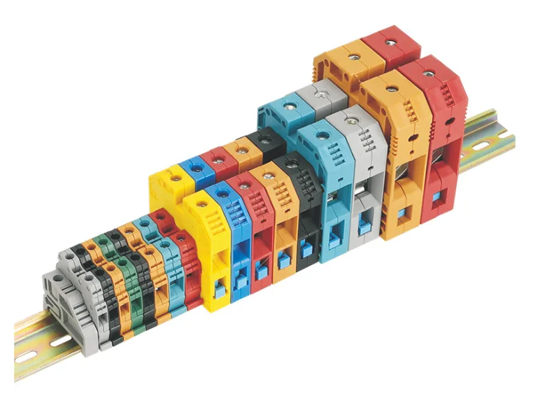
MRK terminal blocks represent a sophisticated approach to electrical connection management, combining robust mechanical design with superior electrical performance. These DIN rail-mounted components utilize screw-clamp connections to ensure firm wire holding and minimal contact resistance, making them indispensable in applications where reliability and organized wiring are paramount. The series encompasses a comprehensive range of models designed to accommodate wire cross-sections from 2.5 mm² to 120 mm², supporting voltage classes of 750V and 1000V with current ratings spanning 24A to 269A.
The MRK series distinguishes itself through several innovative design features. The symmetrical construction allows mounting to DIN rails in both directions, providing installation flexibility that simplifies panel layout and reduces assembly time. The closed-end design eliminates the need for terminal end plates, delivering cost savings while enhancing electrical isolation. This thoughtful engineering ensures that MRK terminal blocks meet the demanding requirements of modern industrial environments.
Complete Wire Range Specifications
Wire Cross-Section Compatibility
The MRK terminal block series offers exceptional versatility in wire accommodation, supporting an extensive range of conductor sizes to meet diverse application requirements. Understanding the relationship between wire cross-section (measured in mm²), American Wire Gauge (AWG), and current-carrying capacity is essential for proper terminal block selection and safe electrical installations.
The series begins with the compact MRK 2.5 model, designed for smaller wire cross-sections up to 2.5 mm² (approximately 14 AWG). This model excels in control circuit applications where space efficiency and organized wiring are priorities. Moving up the range, the MRK 4, MRK 6, MRK 10, and MRK 16 models progressively accommodate larger conductors, with the MRK 16 supporting wires up to 16 mm² (approximately 6 AWG). These mid-range models serve as workhorses in industrial control panels, handling the majority of signal, control, and moderate power distribution requirements.
For heavy-duty power distribution applications, the MRK 25, MRK 35, MRK 50, MRK 70, MRK 95, and MRK 120 models provide robust connections for large-gauge conductors. The MRK 25 accommodates wires up to 25 mm² (approximately 4 AWG), while the flagship MRK 120 handles conductors up to 120 mm² (approximately 4/0 AWG), making it suitable for main power distribution and high-current applications.
AWG to mm² Conversion Reference
Understanding the relationship between American Wire Gauge (AWG) and metric cross-sectional area (mm²) is crucial for international projects and equipment compatibility. The AWG system uses an inverse numbering scheme where higher numbers indicate smaller wire diameters—a concept that can initially confuse those accustomed to metric measurements.
Common wire sizes and their conversions include: 14 AWG (2.5 mm²), 12 AWG (4.0 mm²), 10 AWG (6.0 mm²), 8 AWG (10 mm²), 6 AWG (16 mm²), 4 AWG (25 mm²), 2 AWG (35 mm²), 1 AWG (50 mm²), 1/0 AWG (70 mm²), 2/0 AWG (95 mm²), and 4/0 AWG (120 mm²). These conversions represent approximate equivalents, as the AWG and metric systems use different calculation methods.
When selecting MRK terminal blocks for projects involving both measurement systems, it’s advisable to verify that the terminal’s wire range accommodates the actual conductor size being used. Using wire outside the specified range can result in poor connections, increased contact resistance, overheating, or mechanical damage to the terminal block.
Current Rating Specifications
Rated Current by Model
The current rating of a terminal block represents the maximum continuous current it can safely carry under specified conditions without exceeding temperature limits or compromising electrical integrity. MRK terminal blocks are engineered with current ratings that align with their wire cross-section capacity, ensuring safe operation across the full range of supported conductor sizes.
The MRK 2.5 model carries a rated current of 24A at 750V, making it ideal for control circuits, sensor connections, and low-power distribution applications. This rating aligns with the current-carrying capacity of 14 AWG wire, which typically handles 15-20A in standard installations. The MRK 4 and MRK 6 models support 32A and 41A respectively, accommodating the increased current capacity of larger conductors while maintaining safe operating temperatures.
Mid-range models demonstrate progressively higher current ratings: the MRK 10 handles 57A, the MRK 16 supports 76A, and the MRK 25 is rated for 101A. These ratings reflect the substantial current-carrying capacity of their respective wire sizes, making them suitable for motor control circuits, heating elements, and moderate power distribution applications.
The heavy-duty models in the MRK series deliver impressive current-handling capabilities. The MRK 35 supports 125A, the MRK 50 handles 150A, the MRK 70 carries 192A, the MRK 95 is rated for 232A, and the flagship MRK 120 achieves 269A. These high-current ratings enable direct connection of main power feeds, large motors, and other high-power equipment without requiring intermediate distribution points.
Voltage Ratings and Insulation Classes
MRK terminal blocks are available in two primary voltage classes: 750V and 1000V. The 750V rating serves the majority of industrial control and distribution applications, providing adequate voltage margin for systems operating at 480V, 600V, and lower voltages. The 1000V rating addresses specialized applications requiring higher voltage capability, such as certain motor control systems, renewable energy installations, and international markets with different voltage standards.
The voltage rating represents the maximum system voltage the terminal block can safely withstand without risk of insulation breakdown or electrical flashover. Industry best practice recommends selecting terminal blocks with voltage ratings at least 125% of the maximum operating voltage to provide adequate safety margin and account for voltage transients that may occur during switching operations or fault conditions.
Temperature Considerations and Derating
MRK terminal blocks are designed to operate reliably across a wide temperature range, typically from -40°C to +140°C. This exceptional temperature tolerance ensures consistent performance in harsh industrial environments, from outdoor installations in extreme climates to high-temperature manufacturing facilities.
However, it’s crucial to understand that current ratings are typically specified at a reference temperature of 20°C (68°F). As ambient temperature increases, the terminal block’s ability to dissipate heat diminishes, potentially requiring current derating to maintain safe operating temperatures. Similarly, when multiple terminal blocks are mounted in close proximity on a DIN rail, the cumulative heat generation can elevate temperatures beyond what individual blocks would experience in isolation.
For installations in high-temperature environments or dense terminal block arrays, engineers should consult manufacturer derating curves or apply conservative safety factors. A common approach involves selecting terminal blocks with current ratings 20-30% higher than the calculated maximum circuit current, providing thermal margin that accommodates elevated ambient temperatures and heat accumulation from adjacent components.
Comprehensive Dimensional Specifications
Physical Dimensions by Model
Understanding the precise dimensions of MRK terminal blocks is essential for panel layout, space planning, and ensuring adequate clearances for wire routing and maintenance access. The MRK series employs a modular design philosophy where terminal block width increases proportionally with wire capacity, while maintaining standardized height and depth profiles that simplify panel design.
The compact MRK 2.5 measures 40mm (height) × 40mm (width) × 34.5mm (depth), providing a space-efficient footprint suitable for dense control panel layouts. This compact size allows multiple terminals to be mounted in limited spaces while maintaining adequate spacing for wire management and labeling.
As wire capacity increases, terminal block width expands to accommodate larger screw terminals and wire insertion chambers. The mid-range models maintain similar height and depth profiles while progressively increasing width. The MRK 35, representing a substantial step up in current capacity, measures 51mm (height) × 54mm (width) × 15mm (depth), reflecting the larger internal components required for high-current connections.
DIN Rail Mounting Specifications
All MRK terminal blocks are designed for mounting on standard 35mm DIN rails conforming to EN 60715 specifications. This universal mounting system enables rapid installation and removal without tools, utilizing spring-loaded clips that engage securely with the rail profile. The snap-on mounting mechanism allows terminal blocks to be positioned, repositioned, or removed quickly during installation or maintenance operations.
The DIN rail mounting system offers significant advantages over traditional screw-mounted terminal strips. Installation time is dramatically reduced, as terminal blocks simply snap onto the rail without requiring individual fasteners. Panel modifications are simplified, as terminal blocks can be easily relocated to optimize wire routing or accommodate design changes. The standardized mounting also ensures consistent positioning and alignment, contributing to professional-appearing installations.
Screw Terminal Specifications and Torque Requirements
The screw terminals in MRK terminal blocks utilize precision-engineered fasteners designed to provide optimal clamping force without damaging conductors. Proper torque application is critical for achieving reliable connections that maintain low contact resistance over the terminal block’s service life.
For the MRK 25 model, the specified torque is 2.0 Nm (approximately 18 in-lb). This torque value represents the optimal balance between achieving adequate clamping force to ensure low contact resistance and avoiding over-tightening that could damage wire strands or strip the screw threads.
Using a calibrated torque screwdriver or torque-limiting tool is strongly recommended for professional installations. Under-tightening results in high contact resistance, which generates excessive heat and can lead to connection failure. Over-tightening can damage conductor strands, particularly with stranded wire, reducing the effective cross-sectional area and current-carrying capacity. Proper torque application ensures connections that remain secure and reliable throughout the terminal block’s operational life.
Material Specifications and Construction
Housing Material: Flame-Retardant Polyamide (PA 6.6)
MRK terminal blocks utilize high-quality polyamide 6.6 (PA 6.6, also known as Nylon 6.6) for housing construction. This engineering thermoplastic offers an exceptional combination of properties that make it ideal for electrical applications. PA 6.6 provides excellent electrical insulation characteristics with high dielectric strength, ensuring reliable isolation between adjacent terminals and between conductors and the mounting rail.
The material’s flame-retardant properties meet stringent safety standards, self-extinguishing when exposed to ignition sources and preventing fire propagation within electrical enclosures. This critical safety feature protects personnel and equipment in the event of electrical faults or overheating conditions. PA 6.6 also demonstrates excellent mechanical strength, impact resistance, and dimensional stability across the terminal block’s operating temperature range of -40°C to +140°C.
The material’s resistance to chemicals, oils, and solvents ensures long-term reliability in industrial environments where exposure to various substances is common. Unlike some alternative materials that may degrade or become brittle over time, PA 6.6 maintains its properties throughout extended service periods, contributing to the terminal block’s long operational life and minimal maintenance requirements.
Contact Materials: Copper and CK45 Steel
The electrical contacts within MRK terminal blocks employ a carefully engineered combination of materials optimized for electrical conductivity, mechanical strength, and long-term reliability. The bridge component—the primary current-carrying element that connects adjacent terminals when bridging is required—is manufactured from high-conductivity copper. Copper’s exceptional electrical conductivity (second only to silver among practical conductor materials) ensures minimal voltage drop and heat generation even when carrying rated current.
The contact element that directly interfaces with the conductor wire utilizes CK45 steel, a medium-carbon steel alloy offering superior mechanical properties. This material choice provides the hardness and wear resistance necessary to maintain reliable contact pressure over thousands of connection cycles. The steel contact’s mechanical strength prevents deformation under screw clamping force, ensuring consistent contact pressure that maintains low resistance throughout the terminal block’s service life.
The screw fasteners are manufactured from hardened steel, providing the thread strength necessary to withstand repeated tightening and loosening operations without thread degradation. This robust construction ensures that terminal blocks can be serviced and modified multiple times throughout their operational life without compromising connection integrity.
MRK Terminal Block Model Comparison Table
| Model | Wire Range (mm²) | Wire Range (AWG) | Rated Current (A) | Voltage Rating (V) | Dimensions H×W×D (mm) | Torque (Nm) | Typical Applications |
|---|---|---|---|---|---|---|---|
| MRK 2.5 | 0.5 – 2.5 | 20 – 14 | 24 | 750 | 40 × 40 × 34.5 | 0.5 | Control circuits, sensors, signals |
| MRK 4 | 0.5 – 4 | 20 – 12 | 32 | 750 | 42 × 42 × 36 | 0.8 | Control panels, PLCs, low power |
| MRK 6 | 0.5 – 6 | 20 – 10 | 41 | 750 | 45 × 45 × 38 | 1.0 | Motor controls, lighting circuits |
| MRK 10 | 1.5 – 10 | 16 – 8 | 57 | 750 | 48 × 48 × 40 | 1.5 | Power distribution, motor feeders |
| MRK 16 | 1.5 – 16 | 16 – 6 | 76 | 750 | 50 × 50 × 42 | 1.8 | Heavy equipment, HVAC systems |
| MRK 25 | 2.5 – 25 | 14 – 4 | 101 | 750 | 52 × 52 × 44 | 2.0 | Main distribution, large motors |
| MRK 35 | 4 – 35 | 12 – 2 | 125 | 750/1000 | 51 × 54 × 15 | 2.5 | High-power equipment, feeders |
| MRK 50 | 6 – 50 | 10 – 1 | 150 | 750/1000 | 55 × 58 × 18 | 3.0 | Main power distribution |
| MRK 70 | 10 – 70 | 8 – 1/0 | 192 | 750/1000 | 60 × 62 × 20 | 3.5 | Heavy industrial loads |
| MRK 95 | 16 – 95 | 6 – 2/0 | 232 | 750/1000 | 65 × 68 × 22 | 4.0 | Main service entrance |
| MRK 120 | 25 – 120 | 4 – 4/0 | 269 | 750/1000 | 70 × 72 × 25 | 4.5 | Primary distribution, substations |
Selection Criteria and Best Practices
Matching Wire Size to Current Requirements
Proper terminal block selection begins with accurately determining the circuit’s maximum operating current and the wire gauge required to safely carry that current. The relationship between wire size and current capacity is governed by the conductor’s cross-sectional area, material (copper or aluminum), insulation type, installation method, and ambient temperature.
As a fundamental principle, both the wire and the terminal block must be rated for at least 125% of the circuit’s maximum continuous current. This safety margin accounts for normal current variations, provides thermal headroom, and ensures compliance with electrical codes. For circuits with significant inrush currents—such as motor starters, transformer primaries, or capacitive loads—additional derating may be necessary to prevent nuisance tripping or component stress.
When selecting MRK terminal blocks, verify that the model’s wire range encompasses the conductor size being used and that the current rating exceeds the circuit’s maximum current by an adequate margin. For example, a 30A circuit using 10 AWG (6 mm²) wire would appropriately utilize an MRK 10 terminal block (rated for 57A), providing substantial thermal margin and ensuring long-term reliability.
Voltage Rating Considerations
The terminal block’s voltage rating must exceed the system’s maximum operating voltage with adequate margin to accommodate transients and provide safety clearance. For standard 480V three-phase systems, the 750V rating of MRK terminal blocks provides appropriate margin. For 600V systems or applications with significant voltage transients, the 1000V models offer additional safety margin.
It’s important to recognize that voltage rating relates to insulation capability and clearance distances, not current-carrying capacity. A terminal block with adequate current rating but insufficient voltage rating represents a serious safety hazard, as insulation breakdown can occur even when current levels are well within the terminal’s capacity. Always verify that the voltage rating meets or exceeds system requirements.
Environmental and Application-Specific Factors
The operating environment significantly influences terminal block selection and performance. MRK terminal blocks’ wide temperature range (-40°C to +140°C) accommodates most industrial environments, but extreme conditions may require additional consideration. High-temperature applications, such as those near heat-generating equipment or in hot climates, may necessitate current derating or selection of larger terminal blocks to maintain safe operating temperatures.
Vibration exposure is another critical factor. While MRK terminal blocks’ screw-clamp design provides secure wire retention, applications subject to continuous vibration—such as mobile equipment or machinery-mounted panels—benefit from periodic inspection and retorquing of connections. Some installations may warrant the use of lock washers or thread-locking compounds to prevent screw loosening over time.
Chemical exposure, humidity, and contamination potential also influence terminal block selection. The PA 6.6 housing material provides excellent resistance to most industrial chemicals, oils, and solvents, but extreme exposure conditions may require additional protective measures such as sealed enclosures or conformal coating of connections.
Installation Guidelines and Professional Practices
Proper Wire Preparation
Achieving reliable terminal block connections begins with proper wire preparation. For solid conductors, ensure the wire end is cut cleanly and squarely, with no nicks or damage that could create stress concentration points. Remove insulation to expose the appropriate conductor length—typically 8-10mm for most MRK models—taking care not to nick or damage conductor strands during stripping.
Stranded conductors require particular attention to prevent strand separation and ensure all strands are captured within the terminal clamp. For optimal results, twist the conductor strands tightly together after stripping, or use ferrules (wire end sleeves) to consolidate strands and provide a solid termination surface. Ferrules are particularly recommended for fine-stranded wire (Class 5 or Class 6 conductors) to prevent strand breakage and ensure reliable contact.
Connection Technique and Torque Application
Insert the prepared conductor fully into the terminal block’s wire chamber, ensuring it seats completely against the back stop. This full insertion is critical for achieving proper contact with the clamping mechanism and preventing partial connections that could lead to high resistance and overheating. Tighten the screw terminal to the specified torque using a calibrated torque screwdriver or torque-limiting tool.
After tightening, perform a gentle pull test on the conductor to verify secure retention. A properly terminated wire should not pull free or move within the terminal under moderate force. If the conductor pulls out or moves, remove it, inspect for damage, and re-terminate with proper technique.
Labeling and Documentation
Professional installations incorporate comprehensive labeling that identifies each terminal’s function, circuit designation, and destination. MRK terminal blocks feature labeling systems compatible with standard marking strips and tags, enabling clear identification that simplifies troubleshooting and maintenance. Consistent labeling conventions across the installation reduce errors during commissioning and facilitate efficient service operations throughout the system’s life.
Maintain accurate documentation including terminal block schedules, wiring diagrams, and as-built drawings that reflect the actual installation. This documentation proves invaluable during troubleshooting, modifications, and system expansions, reducing downtime and preventing errors that could compromise safety or functionality.
Standards Compliance and Certifications
MRK terminal blocks are manufactured in compliance with international standards governing terminal block design, testing, and performance. The primary applicable standard is EN 60947-7-1 (IEC 60947-7-1), which specifies requirements for screw-type and screwless-type terminal blocks for copper conductors. This comprehensive standard addresses electrical ratings, temperature rise limits, mechanical strength, insulation properties, and environmental performance.
Compliance with these standards ensures that MRK terminal blocks have undergone rigorous testing including current-carrying capacity verification, temperature rise measurement, short-circuit withstand capability, mechanical strength testing, and dielectric strength verification. Products meeting these standards provide assurance of safe, reliable performance when applied within their specified ratings.
Maintenance and Long-Term Reliability
Periodic Inspection Recommendations
While MRK terminal blocks are designed for long-term reliability with minimal maintenance, periodic inspection helps identify potential issues before they lead to failures. Recommended inspection intervals vary based on application severity, environmental conditions, and criticality, but annual inspections represent a reasonable baseline for most industrial installations.
During inspections, visually examine terminal blocks for signs of overheating (discoloration, melted housing, or burnt insulation), mechanical damage, contamination buildup, or loose connections. Use thermal imaging cameras to identify terminals operating at elevated temperatures, which may indicate loose connections, undersized conductors, or overloading. Address any anomalies promptly to prevent progression to failure.
Connection Retorquing
Electrical connections can loosen over time due to thermal cycling, vibration, and conductor creep (particularly with aluminum conductors). Periodic retorquing of terminal screws helps maintain optimal contact pressure and low resistance. For critical applications or harsh environments, consider retorquing connections during annual maintenance or after the first year of operation, when initial settling is most likely to occur. citation
Frequently Asked Questions (FAQ)
Q1: What is the difference between the 750V and 1000V rated MRK terminal blocks?
The voltage rating indicates the maximum system voltage the terminal block can safely withstand. The 750V rating suits most industrial applications including 480V and 600V systems. The 1000V rating provides additional safety margin for specialized applications, higher voltage systems, or installations subject to significant voltage transients. Both ratings offer identical current-carrying capacity for the same model size.
Q2: Can I use stranded wire in MRK terminal blocks without ferrules?
Yes, MRK terminal blocks accept both solid and stranded conductors. However, ferrules (wire end sleeves) are strongly recommended for stranded wire, particularly fine-stranded conductors. Ferrules consolidate strands, prevent strand breakage, and ensure all strands are captured within the terminal clamp, resulting in more reliable connections with lower contact resistance.
Q3: How do I calculate the correct terminal block size for my application?
First, determine your circuit’s maximum continuous current and select wire size rated for at least 125% of that current. Then choose an MRK terminal block model whose wire range accommodates your conductor size and whose current rating exceeds your circuit current by at least 25%. For example, a 40A circuit using 8 AWG (10 mm²) wire would require an MRK 10 or larger terminal block.
Q4: What torque should I use when tightening terminal screws?
Always use the manufacturer’s specified torque for each model. For example, the MRK 25 requires 2.0 Nm. Using a calibrated torque screwdriver ensures proper clamping force without over-tightening. Under-tightening causes high resistance and overheating; over-tightening can damage conductors and strip threads.
Q5: Can MRK terminal blocks be used with aluminum conductors?
While MRK terminal blocks can physically accommodate aluminum conductors within their specified wire range, aluminum requires special considerations including anti-oxidant compound application, proper torque (often different from copper), and more frequent inspection due to aluminum’s greater thermal expansion and creep characteristics. Verify compatibility and follow manufacturer guidelines when using aluminum conductors.
Q6: How many wires can I connect to a single MRK terminal block?
Most MRK terminal blocks are designed for one wire per side (two wires total per terminal). Some models may accommodate two wires on one side if both wires are at the smaller end of the wire range, but this reduces the effective current rating. Always consult specifications and avoid exceeding the terminal’s wire capacity or current rating.
Q7: What is the expected service life of MRK terminal blocks?
When properly installed within their ratings and maintained according to recommendations, MRK terminal blocks provide decades of reliable service. The flame-retardant PA 6.6 housing and robust contact materials resist degradation from environmental exposure, thermal cycling, and normal wear. Service life is primarily limited by application severity and environmental factors rather than inherent material limitations.
Q8: Are MRK terminal blocks suitable for outdoor installations?
MRK terminal blocks’ wide temperature range (-40°C to +140°C) and chemical-resistant materials make them suitable for outdoor use when installed in appropriate enclosures that provide protection from direct weather exposure. The terminal blocks themselves are not weatherproof, so they must be housed in NEMA-rated or IP-rated enclosures appropriate for the installation environment.
