
MRK Terminal Blocks for Control Panel Wiring: Best Practices and Solutions

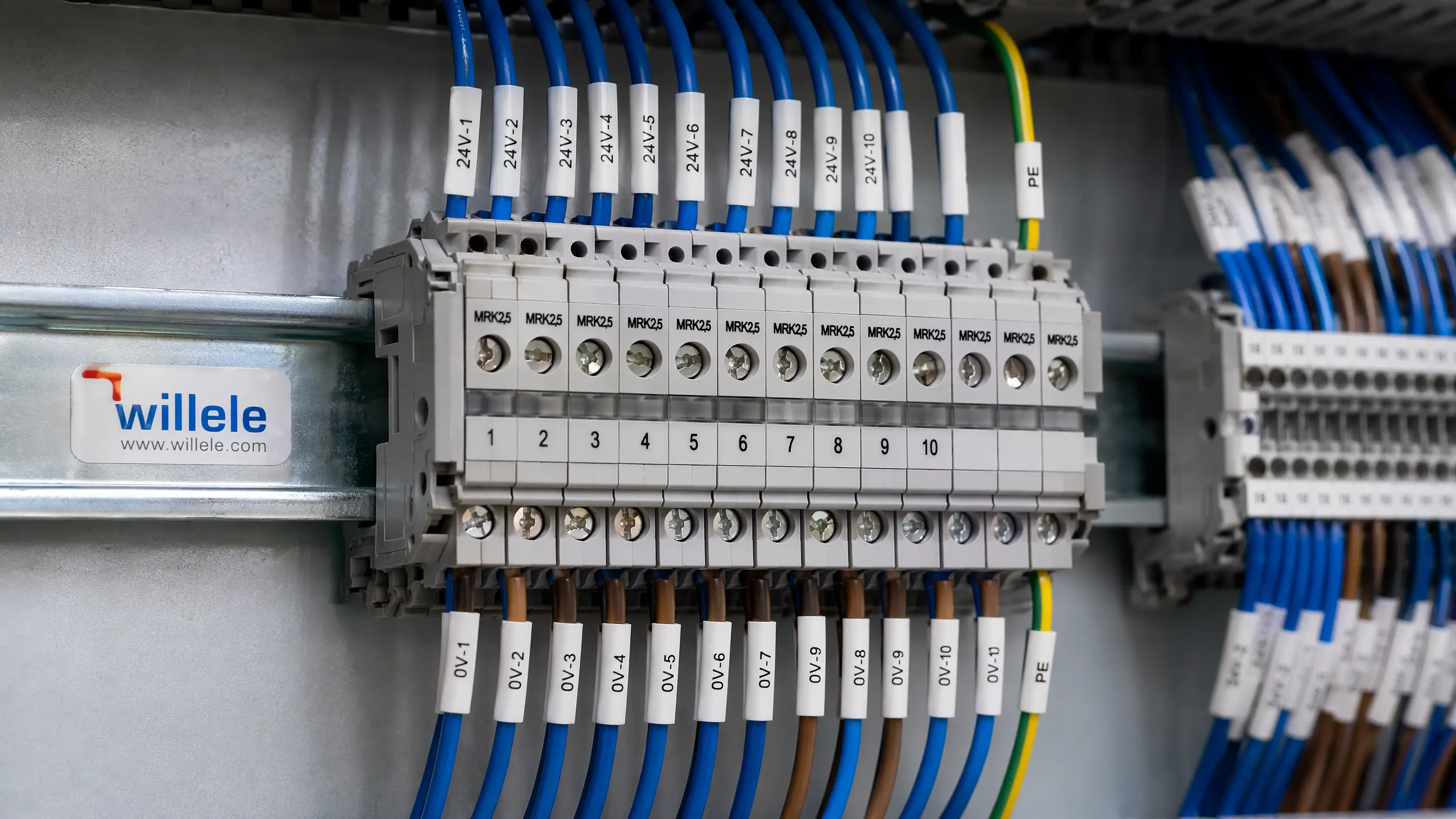
In modern industrial automation and electrical control systems, the reliability of every connection point directly impacts operational efficiency and safety. MRK terminal blocks have emerged as a trusted solution for control panel wiring, offering robust performance, modular flexibility, and compliance with international standards. This comprehensive guide explores best practices for implementing MRK terminal blocks in control panel applications, helping engineers and technicians optimize their electrical installations.
Understanding MRK Terminal Blocks
MRK terminal blocks are DIN rail-mounted connection devices designed to provide secure, organized, and maintainable wiring solutions in electrical control panels and distribution boards. These modular components serve as central connection points where incoming and outgoing wires meet, eliminating the need for permanent splices or soldering while maintaining excellent electrical continuity.
The MRK series encompasses a comprehensive range of terminal block types, each engineered for specific applications. Standard feed-through blocks handle general-purpose connections, while specialized variants include double-level blocks for space optimization, fused blocks for integrated overcurrent protection, test disconnect blocks for circuit isolation during maintenance, and dedicated earth blocks for safety grounding. This versatility makes MRK terminal blocks suitable for diverse industrial environments, from manufacturing automation to building management systems.
Key Technical Specifications
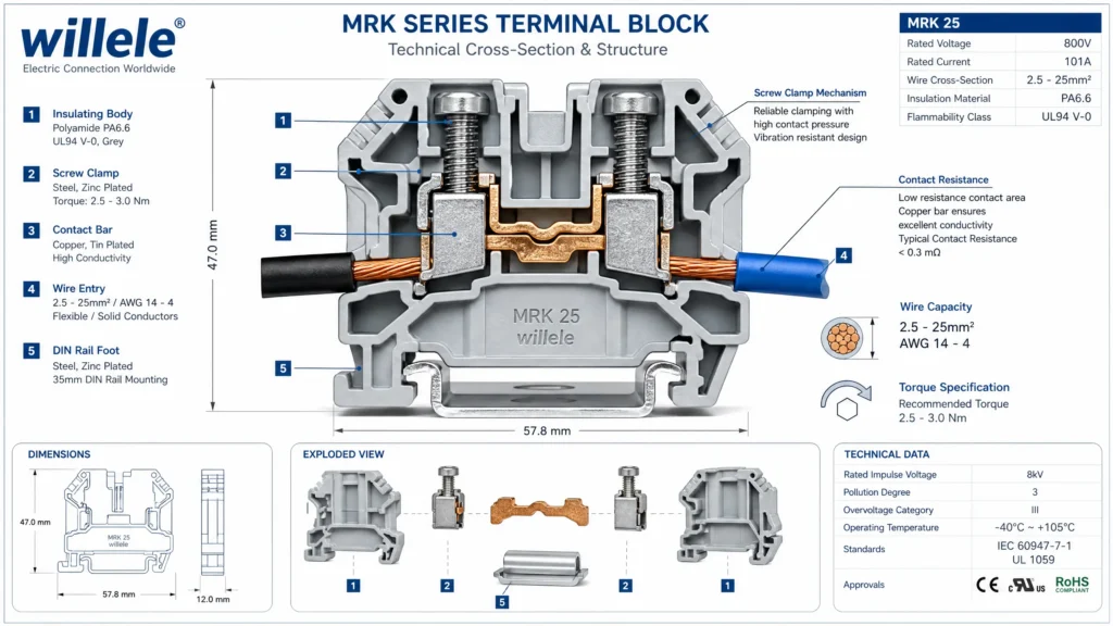
MRK terminal blocks are available in multiple wire cross-section capacities to accommodate different current requirements. The series typically includes models rated for 2.5mm², 4mm², 6mm², 10mm², 16mm², and 25mm² conductors, with corresponding current ratings ranging from approximately 24A to 101A. The largest models in the series can handle conductors up to 35mm² for heavy-duty power distribution applications.
Construction materials reflect the demanding requirements of industrial environments. The insulating body is manufactured from polyamide PA6.6, a high-performance engineering thermoplastic that provides excellent electrical insulation, mechanical strength, and chemical resistance. Contact elements are typically fabricated from copper or CK45 steel with copper plating, ensuring low contact resistance and reliable current transfer. These materials enable MRK terminal blocks to operate across a wide temperature range, typically from -40°C to +140°C, making them suitable for both climate-controlled facilities and harsh industrial environments.
The electrical ratings of MRK terminal blocks are equally impressive. Standard models support nominal voltages up to 750V, with proper creepage and clearance distances designed to prevent electrical breakdown. The screw-clamp connection system requires specific tightening torques—typically 2.0 Nm for larger models—to ensure optimal contact pressure without damaging the conductor or terminal components.
Design Advantages of MRK Terminal Blocks
One of the most significant design innovations in the MRK series is the symmetrical body construction. Unlike asymmetrical designs that require careful orientation during installation, MRK terminal blocks can be mounted in either direction without affecting functionality. This feature substantially reduces installation time and eliminates a common source of wiring errors, particularly valuable when panel builders are working under tight deadlines.
The integrated labeling system represents another thoughtful design element. MRK terminal blocks incorporate dedicated spaces for identification markers, allowing technicians to clearly label each connection point. This capability is essential for maintaining organized control panels and dramatically reduces troubleshooting time when issues arise. Proper labeling also ensures compliance with electrical codes and standards that mandate clear identification of all connection points.
The modular nature of MRK terminal blocks provides exceptional flexibility for panel design. Individual blocks snap onto standard 35mm DIN rail (EN 60715) and can be arranged in any sequence to match the specific requirements of each application. This modularity extends to accessory components: jumper bars can link multiple terminals for common power distribution, separation plates can create visual and functional groupings, and end stops secure the entire assembly. The ability to reconfigure terminal arrangements without specialized tools or extensive rewiring makes MRK blocks ideal for applications that may require future modifications or expansions.
Best Practices for MRK Terminal Block Installation
Pre-Installation Planning
Successful control panel wiring begins long before the first wire is stripped. Thorough planning during the design phase prevents costly mistakes and ensures a professional, maintainable installation. Start by creating a detailed wiring diagram that shows every connection point, including terminal block designations, wire numbers, and signal types. This documentation serves as the blueprint for installation and becomes invaluable during commissioning and future maintenance.
Establish a logical numbering scheme before panel construction begins. Common conventions separate different signal types into distinct numeric ranges. For PLC input/output addressing, many facilities use formulas such as 1000 + (Slot Number × 100) + Point Number, which eliminates the need for conversion charts during wiring and troubleshooting. Group terminal blocks by voltage class and function using designation prefixes: “TB” for general terminal blocks, “PE” for protective earth connections, “AI” for analog inputs, “DO” for digital outputs, and so forth.
Capacity planning is equally critical. A common mistake in panel design is failing to include adequate spare terminals. Industry best practice recommends planning for 10-15% spare I/O capacity, plus 2-4 dedicated spare terminals each for common connections like +24VDC power, common ground, and AC mains. These spares prove invaluable during commissioning when unexpected field devices need to be added, or during troubleshooting when temporary connections are necessary.
DIN Rail Mounting Procedures
Begin by securely mounting the 35mm top-hat DIN rail to the panel backplate. The rail must be level and firmly fastened, as it will support the weight of all terminal blocks and the mechanical stress of wire connections. Use appropriate mounting hardware for the panel material—self-tapping screws for metal panels, or machine screws with backing plates for fiberglass or plastic enclosures.
Before mounting terminal blocks, organize them in the planned sequence outside the panel. This dry-fit process allows you to verify spacing, confirm that all necessary block types are available, and identify any potential issues before components are permanently installed. When snapping blocks onto the DIN rail, ensure each block is fully seated—you should hear and feel a distinct click as the mounting foot engages the rail profile.
Position terminal blocks to allow adequate space for wire bending and routing. Wires should not be forced into sharp bends immediately adjacent to terminal connections, as this can cause conductor fatigue and eventual failure. The IEC 60947-7-1 standard recommends securing cables within 15 cm of terminal connections to prevent mechanical stress on the connection point itself.
Wire Preparation and Connection
Proper wire preparation is fundamental to reliable terminal block connections. Strip wire insulation to the length specified by the terminal block manufacturer, typically 9-11mm for most MRK models. Stripping too much insulation exposes excessive bare conductor that could contact adjacent terminals or grounded surfaces; stripping too little prevents the conductor from fully engaging the terminal’s contact area.
For stranded wire, the use of ferrules is strongly recommended, particularly for conductors larger than 1.5mm². Ferrules are crimped metal sleeves that consolidate stranded wire into a solid termination, preventing individual strands from escaping the terminal connection and potentially causing short circuits. Ferrules also increase the effective contact area and reduce contact resistance, improving long-term reliability.
When inserting wires into screw-clamp terminals, ensure the conductor is fully inserted into the terminal cavity before tightening the screw. The screw should compress the conductor against the terminal’s contact bar, not merely trap the insulation. Tighten terminal screws to the manufacturer’s specified torque—typically 0.5-0.6 Nm for smaller terminals (2.5-4mm²) and up to 2.0 Nm for larger models (16-25mm²). Under-tightening results in high contact resistance, heat generation, and potential connection failure; over-tightening can damage the terminal mechanism or crush the conductor.
Safety and Standards Compliance
All control panel wiring must adhere to applicable electrical codes and standards. MRK terminal blocks designed for industrial applications should comply with IEC 60947-7-1 (the international standard for terminal blocks for industrial use) and carry appropriate certifications such as UL recognition or CE marking. These certifications confirm that the products have passed rigorous testing for electrical insulation, temperature rise, mechanical strength, and flammability resistance.
Follow established color-coding conventions for all wiring. In most jurisdictions, protective earth conductors must be green/yellow (or green), neutral conductors should be light blue, and phase conductors are typically brown, black, or gray. Consistent color coding reduces the risk of wiring errors and makes troubleshooting significantly easier. When working with control circuits, establish and document color conventions for different signal types—for example, red for +24VDC, blue for 0VDC common, and other colors for various signal types.
Use insulated tools when working in energized panels, though best practice dictates that all wiring work should be performed with power disconnected and appropriate lockout/tagout procedures in place. Verify that all connections are secure and properly insulated before energizing the panel. After installation, conduct continuity testing to verify correct connections and insulation resistance testing to confirm adequate isolation between circuits.
Optimizing Control Panel Layouts with MRK Terminal Blocks
Functional Grouping Strategies
Organizing terminal blocks by function and voltage level creates panels that are intuitive to understand and maintain. Separate high-voltage power distribution terminals from low-voltage control circuits, and clearly mark the boundaries between different voltage zones. This separation reduces the risk of accidental contact between incompatible circuits and simplifies compliance with electrical codes that mandate specific spacing between circuits of different voltage classes.
Within each voltage zone, group terminals by function. Position all input terminals together, all output terminals together, and all power supply terminals together. This logical organization allows technicians to quickly locate specific connection points without tracing wires through the entire panel. Many experienced panel designers create distinct terminal block “neighborhoods” for different subsystems—one group for motor control circuits, another for sensor inputs, another for communication interfaces, and so forth.
Consider the physical workflow during installation and maintenance. Position terminal blocks that will receive field wiring near the cable entry points to minimize wire length and routing complexity. Place terminals that connect to internal panel components (PLCs, power supplies, relays) near those devices. This thoughtful positioning reduces wire congestion, improves airflow within the panel, and makes the installation process more efficient.
Wire Management and Documentation
Even the best terminal block layout can be undermined by poor wire management. Use wire duct or cable tray to route wires in organized bundles between terminal blocks and devices. Secure wires at regular intervals to prevent sagging or movement that could stress connections. Maintain adequate separation between power wiring and signal wiring to minimize electromagnetic interference.
Label both ends of every wire with permanent, legible identification. Heat-shrink labels or self-laminating wire markers provide durable identification that withstands the industrial environment. Wire numbers should correspond to terminal designations shown on the wiring diagram, creating a clear correspondence between documentation and physical installation. This dual labeling—at both the terminal block and at the device connection—enables technicians to trace circuits from either end without needing to physically follow wires through the entire panel.
Create and maintain accurate as-built documentation. Even with perfect planning, field changes inevitably occur during installation and commissioning. Document these changes immediately, updating wiring diagrams and terminal lists to reflect the actual installation. This living documentation ensures that future maintenance and modifications are based on accurate information rather than outdated plans.
MRK Terminal Block Selection Guide
Choosing the appropriate MRK terminal block for each application requires careful consideration of several factors. The following comparison table summarizes key selection criteria:
| Wire Size (mm²) | Current Rating (A) | Typical Applications | Recommended Torque (Nm) |
|---|---|---|---|
| 2.5 | 24 | Control circuits, sensor wiring, PLC I/O | 0.5-0.6 |
| 4 | 32 | Control circuits, small loads, 24VDC distribution | 0.5-0.6 |
| 6 | 41 | Medium control loads, relay coils, solenoid valves | 0.8-1.0 |
| 10 | 57 | Motor control circuits, heavier loads | 1.2-1.5 |
| 16 | 76 | Power distribution, large motor circuits | 1.5-2.0 |
| 25 | 101 | Main power feeds, high-current distribution | 2.0 |
Connection Technology Comparison
MRK terminal blocks are available with different connection technologies, each offering distinct advantages:
Screw-Clamp Connections remain the most common and versatile option. They provide robust, vibration-resistant connections suitable for both solid and stranded conductors across a wide range of wire sizes. Screw terminals accommodate minor variations in wire preparation and can be easily verified visually. The connection can be loosened and retightened multiple times without degradation, making them ideal for applications that may require periodic modifications.
Spring-Clamp (Push-In) Connections offer faster installation, particularly valuable in high-density panels or when installing large numbers of connections. Prepared wires are simply inserted into the terminal opening, where a spring mechanism grips the conductor. This tool-free connection method reduces installation time and eliminates concerns about proper torque application. However, spring-clamp terminals typically require more precise wire preparation and may have more restrictive wire size ranges compared to screw-clamp designs.
Insulation Displacement Connections (IDC) provide the fastest connection method for specific wire types, though they are less common in MRK-style terminal blocks. IDC terminals use sharp contacts that pierce wire insulation to make electrical contact, eliminating the need for wire stripping. This technology is primarily used in high-volume applications with standardized wire types.
Special-Purpose MRK Terminal Block Variants
Fused Terminal Blocks integrate overcurrent protection directly into the connection point, eliminating the need for separate fuse holders and reducing panel space requirements. These blocks typically accept standard miniature fuses (5×20mm or 5×25mm) rated from 1A to 10A, making them ideal for protecting individual control circuits or small loads. The fused connection appears between the input and output terminals, providing series protection that disconnects the load if current exceeds the fuse rating.
Test Disconnect Terminal Blocks feature a removable link or plug that allows circuits to be isolated without disconnecting wires. This capability is invaluable during commissioning and troubleshooting, enabling technicians to measure signals, inject test signals, or verify circuit operation without disturbing physical connections. Test disconnect blocks are particularly useful for current transformer circuits, where opening the circuit under load could generate dangerous voltages.
Multi-Level Terminal Blocks stack two, three, or even four independent connection points in the space normally occupied by a single terminal. This vertical stacking dramatically increases connection density in space-constrained panels. However, multi-level blocks can complicate wire routing and may make it difficult to access lower-level terminals once upper levels are wired. Use multi-level blocks judiciously, reserving them for applications where space constraints genuinely require the increased density.
Ground/Earth Terminal Blocks feature specialized designs for protective earth connections. These blocks typically use green or green/yellow insulating bodies for easy identification and may include additional features such as longer creepage distances or reinforced contact areas to ensure reliable grounding. Some earth terminal blocks accept multiple conductors per terminal, allowing several ground wires to be consolidated at a single connection point.
Common Installation Challenges and Solutions
Addressing Wire Size Mismatches
One frequent challenge occurs when the available wire size doesn’t perfectly match the terminal block’s optimal range. Using wire that is too small for the terminal results in inadequate contact pressure and high resistance; wire that is too large may damage the terminal or prevent proper insertion. The solution is to select terminal blocks during the design phase based on the actual wire sizes that will be used, rather than trying to adapt wire to available terminals.
When minor mismatches are unavoidable, ferrules can help bridge the gap. A stranded wire that is slightly undersized for a terminal can be fitted with a ferrule that increases the effective diameter, ensuring proper contact. However, this approach has limits—never force oversized conductors into terminals, as this can damage the terminal mechanism and create safety hazards.
Managing High-Density Installations
Modern control panels often pack significant functionality into compact enclosures, creating challenges for terminal block layout. When space is limited, resist the temptation to overcrowd terminal blocks. Adequate spacing between terminals is essential for proper wire bending, heat dissipation, and maintenance access. If the required number of terminals cannot fit comfortably in the available space, consider using multi-level terminal blocks or redesigning the panel layout to provide additional mounting area.
Another space-saving strategy involves using jumper bars instead of individual wires for common connections. When multiple terminals need to be connected to the same potential (such as a common ground or power supply), a jumper bar provides a cleaner, more reliable connection than daisy-chaining wires between terminals. MRK terminal blocks typically accept plug-in jumper bars that span 2, 3, 4, or more terminals, simplifying installation and reducing wire congestion.
Preventing Vibration-Related Failures
Industrial environments often subject control panels to significant vibration from nearby machinery, which can gradually loosen screw-clamp connections over time. Several strategies mitigate this risk. First, ensure that terminal screws are tightened to the proper torque during installation—this provides sufficient clamping force to resist vibration. Second, consider using terminal blocks specifically designed for high-vibration environments, which may feature enhanced clamping mechanisms or thread-locking features.
For critical applications in severe vibration environments, implement a preventive maintenance program that includes periodic inspection and retightening of terminal connections. Many facilities incorporate this task into annual or semi-annual shutdown maintenance windows. Thermal imaging can also identify developing problems, as loose connections generate excess heat that is readily visible with infrared cameras.
Troubleshooting Connection Issues
When circuits fail to operate correctly, terminal block connections are common culprits. Systematic troubleshooting begins with visual inspection: look for obvious issues such as loose terminal screws, damaged insulation, or conductors that have pulled out of terminals. Use a multimeter to verify continuity through suspected connections and measure voltage at key points to confirm that signals are reaching their destinations.
High resistance in terminal connections manifests as voltage drop under load, reduced current flow, or heat generation at the connection point. If a connection feels warm to the touch or shows discoloration, it likely has inadequate contact pressure. Disconnect power, remove the wire, inspect both the conductor and the terminal for damage, and remake the connection with proper technique and torque.
Maintenance and Long-Term Reliability
Routine Inspection Procedures
Establishing a regular maintenance schedule for terminal block connections prevents many common failures. During scheduled maintenance shutdowns, systematically inspect all terminal blocks for signs of problems. Look for discoloration or melting of the insulating body, which indicates overheating. Check for corrosion on exposed conductors or terminal screws, particularly in humid or chemically aggressive environments. Verify that all terminal screws remain tight—vibration and thermal cycling can gradually loosen connections over time.
Document inspection findings and track trends over time. If certain terminals repeatedly show signs of loosening or overheating, investigate the root cause. The issue might be undersized conductors for the load, improper initial installation, excessive vibration, or environmental factors. Addressing these underlying causes prevents recurring failures and extends the service life of the installation.
Environmental Considerations
MRK terminal blocks are designed for industrial environments, but extreme conditions may require additional protection. In areas with high humidity or potential for water ingress, ensure that the panel enclosure provides adequate protection (typically IP54 or higher). Consider using terminal blocks with enhanced sealing or conformal coating for particularly harsh environments.
Temperature extremes affect terminal block performance. While MRK blocks typically operate across a wide temperature range (-40°C to +140°C), sustained operation at temperature extremes can accelerate aging of insulating materials and affect contact resistance. Ensure adequate ventilation in panel enclosures to prevent excessive heat buildup, and consider thermal management solutions such as ventilation fans or air conditioning for panels in hot environments.
Chemical exposure poses another environmental challenge. The polyamide insulating material used in MRK terminal blocks resists many common industrial chemicals, but prolonged exposure to certain solvents, acids, or bases can cause degradation. When panels will be installed in chemically aggressive environments, verify that the terminal block materials are compatible with the specific chemicals present.
Upgrade and Expansion Strategies
One significant advantage of MRK terminal blocks is the ease with which systems can be expanded or modified. When adding new circuits to an existing panel, additional terminal blocks can be snapped onto the DIN rail adjacent to existing blocks. If the original installation included adequate spare terminals, new connections may not require any additional hardware.
When planning expansions, maintain the same organizational logic used in the original installation. New terminals should follow the established numbering scheme and be grouped with functionally similar connections. Update all documentation to reflect the changes, ensuring that the wiring diagrams and terminal lists remain accurate.
If an existing panel has reached capacity and cannot accommodate additional terminal blocks, consider whether a separate junction box or auxiliary panel might be appropriate. This approach maintains the organization of the original panel while providing space for expansion circuits. Connect the auxiliary panel to the main panel through appropriately sized multiconductor cables, and document the interconnections clearly.
Frequently Asked Questions
Q: What is the difference between MRK terminal blocks and other terminal block brands?
A: MRK terminal blocks are a specific series of DIN rail-mounted terminal blocks known for their symmetrical design, robust screw-clamp connections, and comprehensive product range. While they share fundamental characteristics with other quality terminal blocks, MRK blocks are distinguished by features such as integrated end plates that eliminate the need for separate end stops, modular accessory compatibility, and wide availability in various wire size ranges from 2.5mm² to 35mm².
Q: Can I mix different wire sizes on the same terminal block?
A: Each terminal block model is designed for a specific range of wire sizes. While a terminal rated for 2.5-6mm² might physically accept wires at either end of that range, mixing significantly different wire sizes on the same terminal is not recommended. The smaller wire may not achieve adequate contact pressure, resulting in high resistance and potential overheating. Use terminal blocks appropriately sized for each conductor.
Q: How often should terminal block connections be inspected and retightened?
A: Inspection frequency depends on the operating environment and criticality of the application. For general industrial control panels, annual inspection during scheduled maintenance shutdowns is typically sufficient. Panels in high-vibration environments or critical applications may benefit from semi-annual inspections. New installations should be inspected after the first few weeks of operation, as initial thermal cycling and settling can affect connection tightness.
Q: Are ferrules required for stranded wire connections?
A: While not always strictly required, ferrules are strongly recommended for stranded wire, particularly for conductors larger than 1.5mm². Ferrules prevent individual wire strands from escaping the terminal connection, increase the effective contact area, and provide a more reliable long-term connection. Many industrial standards and best practice guidelines specify ferrule use for stranded conductors in screw-clamp terminals.
Q: What should I do if a terminal block shows signs of overheating?
A: Overheating indicates a problem that must be addressed immediately. Disconnect power and investigate the cause. Common culprits include loose connections (insufficient screw torque), undersized conductors for the load current, or damaged terminal components. Inspect both the conductor and the terminal for damage. If the terminal shows melting or significant discoloration, replace it. Remake the connection with proper technique, ensuring adequate wire size and proper torque, then monitor the connection during initial operation to verify that the problem is resolved.
Q: Can MRK terminal blocks be used in outdoor applications?
A: MRK terminal blocks themselves are designed for use within electrical enclosures and are not rated for direct outdoor exposure. However, they can certainly be used in outdoor applications when installed in appropriately rated enclosures (typically NEMA 4X or IP65/IP66) that protect them from moisture, dust, and environmental contaminants. Ensure that the enclosure provides adequate protection for the specific outdoor environment where it will be installed.
