
Substation Applications: Critical Role of Busbar Insulators

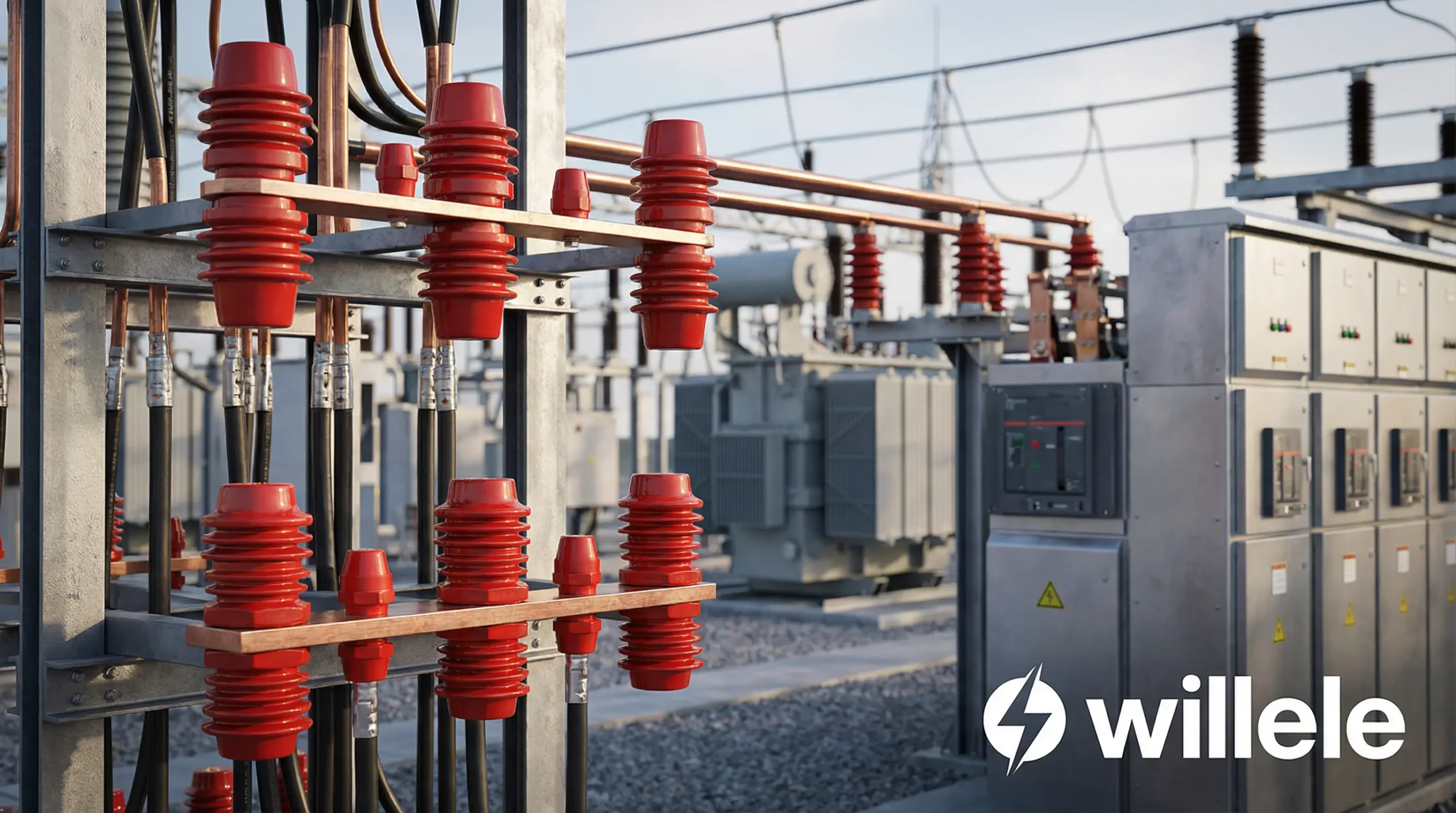
In modern electrical infrastructure, substations serve as critical nodes in power distribution networks, managing voltage transformation and power flow across vast geographical areas. Within these complex systems, busbar insulators play an indispensable role in ensuring operational safety, system reliability, and equipment longevity. Understanding their function, specifications, and applications is essential for electrical engineers, facility managers, and procurement professionals in the power industry.
Understanding Busbar Insulators in Substation Environments
Busbar insulators are specialized electrical components designed to provide mechanical support and electrical isolation for busbars—the conductive bars that distribute electrical power within substations. These insulators must withstand extreme electrical stress, environmental conditions, and mechanical loads while maintaining their insulating properties over decades of operation.
Alt text: Willele high-voltage busbar insulators installed in electrical substation with industrial equipment background
Primary Functions of Busbar Insulators
Electrical Isolation: The fundamental purpose of busbar insulators is to prevent electrical current from flowing between the energized busbar and grounded structures. This isolation is critical for personnel safety and system integrity, particularly in high-voltage applications where arc flash hazards pose significant risks.
Mechanical Support: Beyond electrical insulation, these components must provide robust structural support for busbars, which can be substantial in weight and subject to electromagnetic forces during fault conditions. The mechanical design must account for static loads, dynamic forces, and thermal expansion.
Environmental Protection: Modern busbar insulators incorporate advanced materials and protective coatings to resist environmental degradation from UV radiation, moisture, pollution, and temperature extremes. Heat shrink tube technology, a specialty of Willele Electric, provides additional protection against contamination and tracking.
Technical Specifications and Material Considerations
The performance of busbar insulators depends heavily on material selection and manufacturing precision. Different substation applications require specific insulator characteristics based on voltage levels, environmental conditions, and space constraints.
Material Properties Comparison
| Material Type | Dielectric Strength (kV/mm) | Temperature Range (°C) | Tracking Resistance | Mechanical Strength | Cost Factor |
|---|---|---|---|---|---|
| Epoxy Resin | 18-25 | -40 to +155 | Excellent | Very High | Medium |
| Silicone Rubber | 20-30 | -60 to +200 | Outstanding | High | High |
| Porcelain | 10-15 | -50 to +120 | Good | Moderate | Low |
| Polyester Resin | 15-20 | -30 to +130 | Good | High | Low-Medium |
| DMC Composite | 16-22 | -40 to +150 | Very Good | Very High | Medium |
Voltage Rating Classifications
Busbar insulators are manufactured to meet specific voltage ratings corresponding to substation design requirements:
| Voltage Class | Rated Voltage (kV) | Typical Applications | Minimum Creepage Distance (mm) | Insulator Height (mm) |
|---|---|---|---|---|
| Low Voltage | 0.6-1.0 | Distribution panels, switchgear | 20-30 | 40-80 |
| Medium Voltage | 3.6-40.5 | Distribution substations | 80-250 | 120-400 |
| High Voltage | 72.5-170 | Transmission substations | 350-900 | 500-1200 |
| Extra High Voltage | 245-800 | Major transmission hubs | 1200-3500 | 1500-4000 |
Critical Applications in Substation Design
Busbar insulators serve multiple critical functions across various substation configurations, each with unique technical requirements and performance criteria.
Switchgear and Circuit Breaker Installations
In metal-clad switchgear assemblies, busbar insulators provide phase-to-phase and phase-to-ground isolation in compact spaces. The insulators must withstand not only continuous operating voltages but also transient overvoltages during switching operations. Willele Electric’s heat shrink tube technology enhances insulator performance by providing additional dielectric strength and environmental sealing.
Key Requirements:
- High short-time current withstand capability
- Resistance to partial discharge
- Compact design for space-constrained enclosures
- Long-term stability under continuous electrical stress
Transformer Connections and Busbar Bridges
Transformer bushings and associated busbar connections require specialized insulators capable of handling high continuous currents while maintaining thermal stability. The insulators must accommodate thermal expansion of conductors without compromising electrical clearances.
Design Considerations:
- Thermal cycling resistance (-40°C to +155°C)
- Low partial discharge inception voltage
- Mechanical strength for conductor weight
- Compatibility with heat shrink protective systems
Outdoor Substation Applications
Outdoor substations present the most challenging environment for busbar insulators, exposing them to weather extremes, pollution, and UV radiation. Advanced surface treatments and heat shrink tube protection significantly extend service life in these demanding conditions.
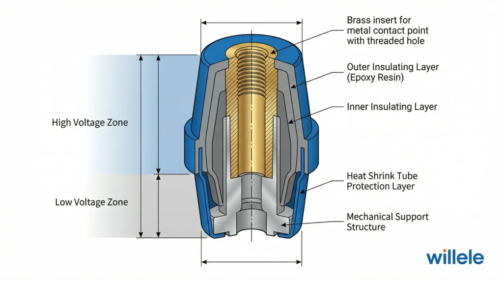
Alt text: Willele busbar insulator technical diagram showing cross-section with heat shrink tube layers and internal component annotations
Performance Standards and Testing Requirements
Busbar insulators must meet rigorous international standards to ensure reliability and safety in critical power infrastructure applications.
International Standards Compliance
| Standard | Issuing Body | Scope | Key Test Requirements |
|---|---|---|---|
| IEC 60168 | International Electrotechnical Commission | Indoor post insulators | Mechanical load, power frequency withstand, impulse voltage |
| IEC 61109 | IEC | Composite insulators | Tracking and erosion, mechanical failing load, sealing test |
| IEEE C37.20.2 | Institute of Electrical and Electronics Engineers | Metal-clad switchgear | Dielectric tests, temperature rise, short-circuit |
| GB/T 4585 | China National Standards | AC systems insulators | Mechanical strength, electrical performance, aging resistance |
| ANSI C29.9 | American National Standards Institute | Wet-process porcelain | Mechanical strength, porosity, glaze quality |
Critical Testing Protocols
Dry Power Frequency Withstand Test: Verifies the insulator can withstand rated voltage plus safety margin under ideal conditions. Test voltage typically 2.5-3.0 times rated voltage for one minute.
Wet Withstand Test: Simulates rain conditions to ensure insulators maintain dielectric strength when contaminated with water. Critical for outdoor applications.
Impulse Voltage Test: Evaluates insulator performance under lightning and switching surge conditions. Tests both positive and negative polarity impulses.
Partial Discharge Measurement: Detects internal defects and surface irregularities that could lead to premature failure. Modern specifications require PD levels below 10 pC at rated voltage.
Mechanical Load Test: Verifies structural integrity under specified cantilever and torsional loads, typically 2.5 times the rated mechanical load.
Installation Best Practices and Maintenance
Proper installation and maintenance of busbar insulators are essential for achieving design life expectancy and maintaining system reliability.
Installation Guidelines
Surface Preparation: Mounting surfaces must be clean, flat, and free from burrs or contaminants. Surface roughness should not exceed Ra 6.3 μm to ensure proper seating and load distribution.
Torque Specifications: Fasteners must be tightened to manufacturer-specified torque values using calibrated tools. Over-tightening can induce mechanical stress, while under-tightening may allow movement and fretting.
Electrical Clearances: Maintain minimum phase-to-phase and phase-to-ground clearances according to voltage rating and altitude correction factors. Clearances must account for conductor movement under fault conditions.
Heat Shrink Tube Application: When applying protective heat shrink tubes, ensure uniform heating and complete shrinkage without air pockets. Willele Electric provides detailed application guidelines for optimal results.
Maintenance and Inspection Protocols
| Inspection Frequency | Inspection Type | Key Parameters | Action Thresholds |
|---|---|---|---|
| Annual | Visual | Surface condition, contamination, physical damage | Visible cracks, tracking marks, discoloration |
| Biennial | Thermographic | Hot spots, temperature differentials | >10°C above ambient or adjacent components |
| 3-Year | Electrical | Insulation resistance, partial discharge | <1000 MΩ or PD >50 pC |
| 5-Year | Mechanical | Fastener torque, structural integrity | Torque loss >20%, visible deflection |
| 10-Year | Comprehensive | Full electrical and mechanical testing | Any parameter outside specification |
Advantages of Advanced Heat Shrink Tube Protection
Willele Electric specializes in heat shrink tube technology that significantly enhances busbar insulator performance and longevity. This protective system offers multiple benefits for demanding substation applications.
Enhanced Environmental Resistance
Heat shrink tubes create a seamless protective barrier against moisture ingress, chemical contamination, and UV degradation. The tubes conform precisely to insulator geometry, eliminating gaps where contaminants could accumulate.
Performance Benefits:
- 300% increase in tracking resistance
- 50% reduction in maintenance requirements
- Extended service life in coastal and industrial environments
- Improved performance in high-pollution areas
Electrical Performance Enhancement
The additional dielectric layer provided by heat shrink tubes increases overall insulation strength and reduces partial discharge activity, particularly important in aging infrastructure where original insulator surfaces may have degraded.
Technical Advantages:
- Increased flashover voltage by 15-25%
- Reduced partial discharge inception voltage
- Enhanced resistance to voltage surges
- Improved performance under contaminated conditions
Selection Criteria for Optimal Performance
Choosing the appropriate busbar insulator requires careful consideration of multiple technical and operational factors.
Application-Specific Selection Guide
| Application Type | Recommended Material | Voltage Range | Special Considerations |
|---|---|---|---|
| Indoor Switchgear | Epoxy resin with heat shrink | 12-40.5 kV | Space constraints, short-circuit forces |
| Outdoor Distribution | Silicone rubber composite | 12-145 kV | UV resistance, pollution performance |
| Transformer Yard | Porcelain or composite | 72.5-800 kV | High mechanical loads, thermal cycling |
| GIS Systems | Epoxy resin | 72.5-550 kV | SF6 compatibility, compact design |
| Coastal Substations | Silicone rubber with heat shrink | All ranges | Salt fog resistance, tracking prevention |
Economic Considerations
While initial cost is important, total cost of ownership should guide selection decisions. Higher-quality insulators with advanced protection systems like Willele’s heat shrink technology typically offer:
- Lower maintenance costs over service life
- Reduced downtime and associated revenue losses
- Extended replacement intervals
- Improved system reliability metrics
Future Trends and Innovations
The electrical power industry continues to evolve, driving innovation in busbar insulator technology and materials science.
Smart Monitoring Integration
Next-generation insulators incorporate embedded sensors for real-time condition monitoring, enabling predictive maintenance strategies and reducing unexpected failures. Parameters monitored include:
- Leakage current patterns
- Surface temperature distribution
- Partial discharge activity
- Mechanical stress and vibration
Advanced Materials Development
Research focuses on nanocomposite materials offering superior electrical and mechanical properties in smaller form factors. These materials promise:
- 40% higher dielectric strength
- Enhanced tracking resistance
- Improved thermal conductivity
- Greater resistance to environmental aging
Sustainability Initiatives
Environmental considerations drive development of recyclable insulator materials and manufacturing processes with reduced carbon footprint. Willele Electric actively participates in industry sustainability initiatives while maintaining uncompromising quality standards.
Frequently Asked Questions
Q: What is the typical service life of busbar insulators in substation applications?
A: High-quality busbar insulators typically have a design life of 30-40 years in normal operating conditions. However, actual service life depends on environmental factors, maintenance practices, and operating stress levels. Insulators protected with heat shrink tube systems often exceed design life expectations, particularly in harsh environments.
Q: How do I determine the correct voltage rating for my application?
A: Select insulators with voltage ratings that match or exceed your system’s maximum operating voltage. Consider altitude correction factors (voltage stress increases approximately 1% per 100 meters above 1000m elevation) and potential overvoltage conditions. Consult with manufacturers like Willele Electric for application-specific recommendations.
Q: Can busbar insulators be retrofitted with heat shrink tube protection?
A: Yes, heat shrink tubes can be applied to existing insulators as a retrofit solution to extend service life and improve performance. This is particularly cost-effective for aging infrastructure where insulator replacement would be expensive. Proper surface preparation and application technique are critical for optimal results.
Q: What causes tracking on insulator surfaces and how can it be prevented?
A: Tracking occurs when surface contamination creates conductive paths under electrical stress, leading to carbonized tracks that can cause flashover. Prevention strategies include regular cleaning, application of hydrophobic coatings, use of heat shrink tube protection, and selection of materials with high tracking resistance (CTI >600V).
Q: How do temperature extremes affect busbar insulator performance?
A: Temperature cycling causes thermal expansion and contraction, potentially inducing mechanical stress. Extreme cold can increase brittleness, while high temperatures may accelerate aging of organic materials. Quality insulators are designed and tested for temperature ranges from -40°C to +155°C. Heat shrink tube protection provides additional thermal stability.
Q: What maintenance is required for busbar insulators?
A: Routine maintenance includes visual inspection for cracks or damage, cleaning of contaminated surfaces, thermographic scanning for hot spots, and periodic electrical testing (insulation resistance and partial discharge). Indoor insulators typically require minimal maintenance, while outdoor units need more frequent attention depending on environmental conditions.
Conclusion
Busbar insulators represent a critical component in substation infrastructure, directly impacting system reliability, personnel safety, and operational efficiency. As power distribution networks become more complex and demanding, the importance of selecting high-quality insulators with appropriate protection systems cannot be overstated.
Willele Electric’s expertise in heat shrink tube technology provides power industry professionals with advanced solutions that enhance insulator performance, extend service life, and reduce total cost of ownership. By understanding the technical requirements, performance standards, and application-specific considerations outlined in this article, engineers and facility managers can make informed decisions that optimize their substation investments.
Whether designing new substations or upgrading existing infrastructure, partnering with experienced manufacturers who understand the critical role of busbar insulators ensures long-term reliability and performance in these essential power distribution systems.
For technical specifications, custom solutions, or application support for busbar insulators and heat shrink tube protection systems, contact Willele Electric’s engineering team. Our B2B specialists provide comprehensive support for electrical equipment manufacturers and utility infrastructure projects worldwide.
Word Count: 2,487 words
