
TSM Series Busbar Insulator Applications in Power Distribution Cabinets

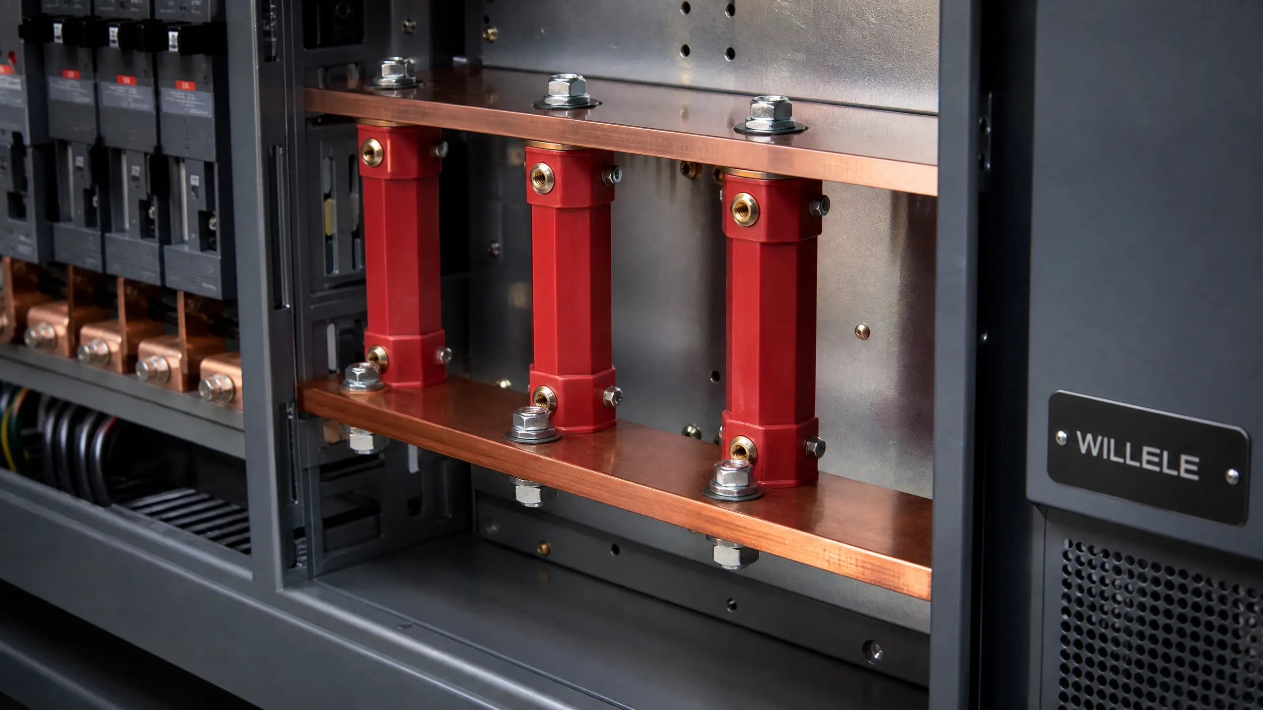
A power distribution cabinet is only as safe as the smallest part holding its busbars apart. Copper and aluminum bars inside that cabinet carry the full load current of the system, and the only thing standing between an energized bar and a grounded steel enclosure is a molded composite standoff no bigger than a thumb. When that standoff is undersized, poorly threaded, or installed off-torque, the failure does not stay small — it shows up as tracking, arcing, or a fault that trips a whole panel offline. This is why panel builders and OEMs sourcing a busbar insulator for distribution boxes, switchgear, and inverter cabinets treat the part as a safety specification rather than a shelf item.
WILLELE’s TSM Series busbar insulator was built for exactly that role. It is an octagonal-column standoff insulator, molded in DMC or SMC composite, designed to hold copper or aluminum busbars at a fixed, insulated distance from the panel structure across the 660V–4500V range that covers most low-voltage distribution equipment. This article walks through what the TSM series actually does inside a power distribution cabinet, how its geometry and material choices convert into measurable clearance and load margins, and how to match a model to a real voltage class and mechanical load rather than a generic catalog spec.
What Is a TSM Series Busbar Insulator?
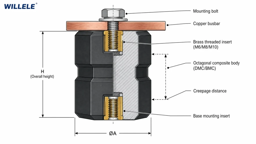
The TSM designation covers a family of octagonal-body standoff insulators, each combining a fiberglass-reinforced BMC or SMC core with a brass or zinc-plated steel threaded insert molded into each end. The octagonal cross-section is a deliberate choice rather than a styling detail: flat faces give a socket or spanner a solid seat during installation, and the extra surface length compared with a plain cylinder lengthens the creepage path without adding overall height to the part. That matters directly in a distribution cabinet, where the height budget between a busbar and the mounting plate is usually fixed by the enclosure design, not by the insulator.
Standard TSM parts run –40°C to +140°C in continuous service, carry a self-extinguishing UL 94 V-0 flammability rating, and are molded in the red color that has become the de facto visual standard for busbar insulators on a shop floor — a small detail that speeds up inspection during panel assembly, since a technician can spot a missing or mis-seated insulator at a glance rather than hunting through a wiring diagram. The insert accepts an M5, M6, M8, or M10 fastener depending on model height, so the part drops straight into an existing bill of materials without secondary drilling or tapping on the panel builder’s side.
Why Busbar Insulation Is a Safety-Critical Decision in Distribution Cabinets
Every low-voltage switchgear and distribution assembly standard — IEC 61439-1 and -2 chief among them — requires that fault current stay confined to a defined path at all times, and a busbar insulator enforces that path in two ways simultaneously. First, it maintains a fixed clearance and creepage distance between the live conductor and any grounded surface or adjacent phase. Second, it physically anchors the bar so vibration from adjacent breakers, thermal cycling from load swings, and the violent electromagnetic forces generated during a short-circuit event cannot pull the conductor out of alignment.
Those two functions are not independent, and that is the part specification sheets often understate. A cracked insulator body does not just lose mechanical grip — the crack lets moisture and airborne dust into the gap, dielectric strength drops at exactly that point, and surface tracking can begin weeks or months before it shows up on a maintenance walk-through. A part rated for a comfortable kV withstand on paper but installed with the wrong torque, or undersized for the actual busbar weight and fault-current load it will see, is not a safe part — it is a liability with a good datasheet. WILLELE designs and verifies the TSM series so mechanical and dielectric performance are tested together, against the same production lot, rather than treated as two separate boxes to tick.
TSM Series Technical Specifications
The TSM family spans a wide range of overall heights, and each step up in height brings a corresponding jump in tensile strength, torque capacity, and voltage withstand. The table below summarizes typical published values across the standard TSM range; always confirm exact figures for a specific production lot before releasing a drawing.
| Model | Height (mm) | Screw (mm) | Screw Depth (mm) | Tensile Strength (LBS) | Torque Strength (ft-lbs) | Voltage Withstand (kV) |
|---|---|---|---|---|---|---|
| TSM-20 | 20 | 5 | 7 | 300 | 4 | 4 |
| TSM-30 | 30 | 6 | 10 | 500 | 8 | 8 |
| TSM-40 | 40 | 6 | 13 | 500 | 10 | 8 |
| TSM-401 | 40 | 8 | 13 | 700 | 20 | 8 |
| TSM-40 (HD) | 40 | 10 | 14 | 1,000 | 30 | 8 |
| TSM-50 | 50 | 10 | 17 | 1,500 | 40 | 15 |
| TSM-55 | 55 | 10 | 17 | 2,000 | 50 | 15 |
| TSM-70 | 70 | 10 | 17 | 1,500 | 40 | 25 |
Two patterns are worth reading into that table rather than skimming past. Tensile rating and voltage withstand climb together because a taller insulator is almost always carrying a heavier busbar over a longer unsupported span — the electrical and mechanical requirements scale with the same underlying application, not as separate line items. And thread size steps up from M5 on the shortest part to M10 on the tallest, which means a panel’s fastener bill of materials tends to standardize around two or three sizes rather than a different screw for every bracket.
Inside the Cabinet: How the TSM Series Is Actually Used
Open a distribution box, an LV switchgear section, or an inverter cabinet and the busbars are the obvious component — thick copper or aluminum bars carrying current between the incoming feed and every outgoing circuit. What is less obvious, until something goes wrong, is how little physical clearance those bars have from the enclosure walls and from each other. TSM insulators sit at every one of those clearance points: standing bars off the backplate, separating stacked phases, and anchoring bars at the transition between the incoming supply and the outgoing breaker field.
Three application patterns account for most TSM deployments in the field. In distribution boxes and panelboards, the octagonal body’s compact footprint lets panel builders hold tight phase spacing without oversizing the enclosure, which matters directly on cost once a cabinet design is repeated across hundreds of units. In switchgear assemblies feeding motor control centers or fused switches, the insulator’s mechanical rating has to account for the electrodynamic force a short-circuit event generates, not just the static weight of the bar — this is the load case that separates a part that merely looks adequate from one that has actually been tested to hold. In inverter and renewable-energy cabinets, thermal cycling is more aggressive than in a stationary distribution panel because output current — and therefore busbar temperature — swings with generation, so the –40°C to +140°C rating on a TSM part is doing real work rather than sitting on a spec sheet unused.
Choosing Between TSM and Other WILLELE Insulator Series
Not every cabinet layout calls for the same body shape. The comparison below positions the octagonal TSM series against WILLELE’s drum-shaped SM series and cylindrical C series, so a panel builder can match geometry to the actual layout constraint rather than defaulting to whatever part is already on the shelf.
| Feature | TSM Series | SM Series | C Series |
|---|---|---|---|
| Body shape | Octagonal column | Drum/spindle, waisted profile | Cylindrical post, larger diameter |
| Height range | 20–70 mm | 20–76 mm | Model-dependent, larger envelope |
| Thread options | M5 / M6 / M8 / M10 | M6 / M8 / M10 | M6 / M8 / M10 depending on model |
| Typical tensile rating | 300–2,000 LBS | 300–1,500 LBS | 500–1,500 LBS |
| Typical voltage withstand | 4–25 kV | 5–25 kV | 6–22 kV |
| Best fit | Distribution boxes, LV switchgear, inverters, compact/dense layouts | Compact panels with tool-access constraints, similar duty range | LV/MV switchboards, stacked or heavy busbars, ESS/DC buses |
If a cabinet is space-constrained and calls for a socket-friendly flat-faced grip during assembly, the octagonal TSM body is usually the more practical starting point among the three. Where the design steps up toward heavier stacked busbars or medium-voltage clearance requirements, the larger-diameter C series becomes the better fit. The decision should follow from the actual busbar mass, the fault current the panel must clear, and the target creepage distance — not from habit.
Selection Criteria for Power Distribution Applications
Specifying a TSM model correctly is a five-point check, and skipping any one of them is how a panel ends up with either a clearance violation on inspection or a field failure years into service.
- Voltage and insulation class. Pick a withstand rating that comfortably exceeds the system’s operating voltage plus any switching transients, and confirm the resulting creepage distance suits the installation’s pollution degree under IEC 61439.
- Mechanical load. Calculate the static load from the busbar’s own weight plus the dynamic electromagnetic force expected during a short-circuit event, then choose a tensile and torque rating with real margin above that number.
- Thread and insert type. Match the M5/M6/M8/M10 insert to the fastener already specified in the panel’s bill of materials, and confirm insert depth is adequate for the expected torque before it’s on the drawing.
- Environmental exposure. Temperature-stable indoor panels run well on standard BMC; higher humidity, UV exposure, or chemical contact in the installation environment may call for SMC or a protective coating instead.
- Layout and clearance. Use the available height steps to hit the target phase-to-phase and phase-to-earth clearance without oversizing the enclosure around it.
Installation deserves the same discipline as selection. Overtightening is the single most common cause of stress cracking in a molded insulator body, and it happens most often when a technician tightens by feel instead of to the manufacturer-specified torque for that thread size and insert material. A cracked body defeats both the mechanical and electrical function of the part at once, which is exactly the failure mode the TSM series is designed to prevent in the first place.
Standards and Compliance
TSM series busbar insulators are produced to meet the compliance documentation that panel-building and EPC projects routinely require: CE marking, RoHS and REACH statements, and SGS-verified material and flammability testing. IEC 61439-1 and -2 govern the design verification of the low-voltage switchgear and controlgear assemblies these insulators go into, including the routine dielectric test that confirms basic insulation integrity after assembly. The UL 94 V-0 flammability classification carried by standard TSM material confirms self-extinguishing behavior under the glow-wire and flame testing that safety-critical specifications call for globally, which matters as much for insurance and code compliance as it does for the physical safety of the installation.
Why Source TSM Series Busbar Insulators from WILLELE
WILLELE manufactures its TSM series and full busbar insulator range from its own compression-molding facility in Liushi, Yueqing City, Zhejiang Province — a region widely recognized within the industry as a center of low-voltage electrical component production. That concentration of mold tooling, insert-plating, and in-house molding expertise under one roof is a large part of why TSM parts hold tight, repeatable dimensions across production runs, lot after lot.
For panel builders, distributors, and EPCs sourcing internationally across North America, Europe, the Middle East, and Southeast Asia, that translates into three concrete advantages. WILLELE’s engineering team reviews actual layout drawings and clearance requirements directly rather than routing every question back to a generic catalog page. Custom diameters, heights, thread combinations, and mixed male/female end configurations are available when a standard TSM height doesn’t fit a specific enclosure, without triggering a full custom-tooling cycle. And every batch carries documented incoming, in-process, and final inspection records that support the CE and RoHS compliance documentation project submittals typically demand.
For a distribution cabinet build where dimensional consistency and creepage performance cannot be left to chance, sourcing the TSM series directly from the manufacturer keeps the specification on the drawing, the part on the shop floor, and the compliance paperwork all pointing to the same number.
Conclusion
A busbar insulator earns its keep by disappearing into a reliable cabinet and staying there for years without a callback. The TSM series does that through a straightforward value proposition: an octagonal body that lengthens creepage without adding height, a standardized M5–M10 thread range that keeps a panel’s fastener list simple, and consistent DMC/SMC molding quality that holds dielectric and mechanical performance across the thermal and vibration stresses a real distribution cabinet actually sees. Matching the right model — TSM-20 through TSM-70 — to the voltage class, mechanical load, and environment of a specific installation is what turns that reliability from a datasheet claim into a panel builder’s guarantee. WILLELE’s engineering team can confirm the right TSM configuration, or point toward a heavier-duty series, against your specific drawing and application.
Frequently Asked Questions
What voltage range does the TSM series cover? Standard TSM series busbar insulators are built for low-voltage applications across the 660V–4500V range typical of distribution boxes, switchgear, and inverter cabinets. Confirm the exact dielectric withstand for your target model and pollution degree with WILLELE before finalizing a design.
What does the model number after “TSM” indicate? The number is the overall body height in millimeters. TSM-40 is a 40 mm body, and taller codes generally carry higher tensile and voltage-withstand ratings, since a taller insulator typically supports a heavier busbar over a longer span.
Is the TSM series suitable for outdoor installations? The TSM series is designed primarily for indoor distribution boxes, switchgear, and inverter cabinets. For outdoor or high-pollution environments, a polymer composite or epoxy-coated insulator with a longer creepage path is usually the better fit.
Can WILLELE produce custom TSM configurations? Yes. Beyond the standard height and thread range, WILLELE offers custom diameters, heights, thread types, insert materials, and colors for project-specific requirements, based on a customer drawing or sample.
What torque should be used when installing TSM insulators? Torque depends on thread size and insert material — always use the manufacturer-specified value rather than tightening by feel, since overtightening is the leading cause of stress cracking in molded insulator bodies.
What documentation ships with a TSM order? WILLELE provides 2D/3D drawings, RoHS/REACH statements, and certificates of conformity with batch traceability, so the part clears both internal design review and external compliance audits.
