
Understanding Voltage Ratings for Busbar Insulators

Introduction
Understanding voltage ratings for busbar insulators is critical for ensuring electrical safety, system reliability, and regulatory compliance in industrial and commercial power distribution systems. Busbar insulators serve as the foundation for safe electrical installations, providing essential dielectric separation between energized conductors and grounded structures. Selecting insulators with appropriate voltage ratings prevents electrical failures, reduces maintenance costs, and protects both equipment and personnel from potentially catastrophic electrical hazards.
This comprehensive guide explores the technical specifications, standards, and selection criteria that engineers and procurement specialists need when specifying busbar insulators for various voltage applications. Whether you’re designing low-voltage switchgear or high-voltage distribution systems, understanding these fundamental principles will help you make informed decisions that optimize both safety and performance.
BUS BAR INSULATOR & BUS BAR SUPPORTWhat Are Busbar Insulators and Why Voltage Ratings Matter
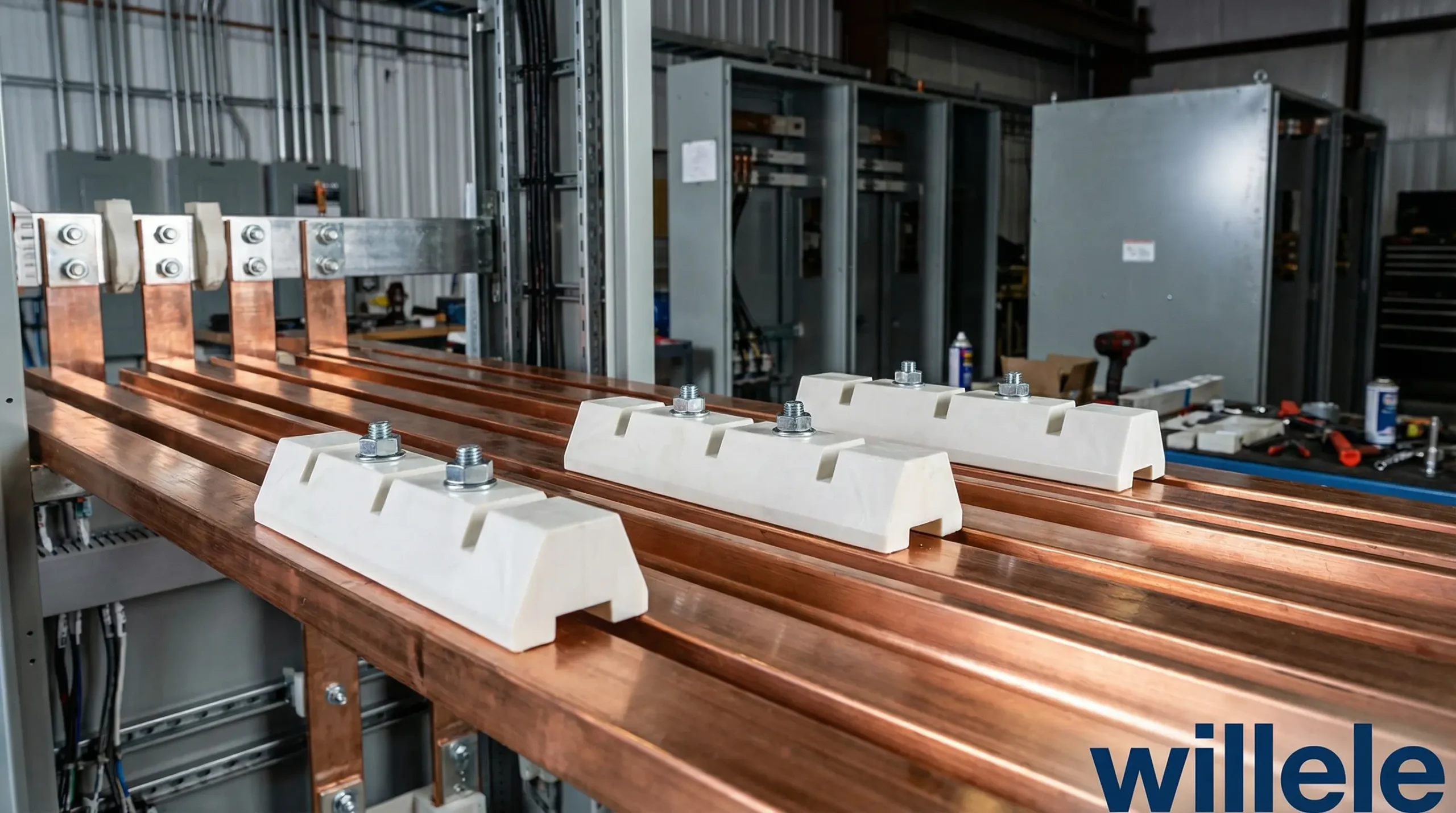
Busbar insulators are specialized electrical components designed to support and electrically isolate conductive busbars from mounting structures, enclosures, and other components. These insulators must withstand the operating voltage while providing mechanical stability and environmental protection throughout their service life.
The voltage rating of a busbar insulator represents the maximum voltage the component can safely handle under specified conditions without electrical breakdown, tracking, or excessive leakage current. This rating isn’t simply a single number—it encompasses multiple parameters including:
- Rated voltage: The maximum continuous operating voltage
- Impulse withstand voltage: The peak voltage the insulator can withstand during transient events
- Test voltage: The voltage applied during factory and field testing
- Pollution severity level: The environmental conditions the rating assumes
Incorrect voltage rating selection can lead to premature insulator failure, creating dangerous fault conditions, production downtime, and potential safety incidents. Understanding voltage ratings for busbar insulators therefore directly impacts system reliability and operational safety.
Voltage Rating Classification and Standards
Primary Voltage Categories
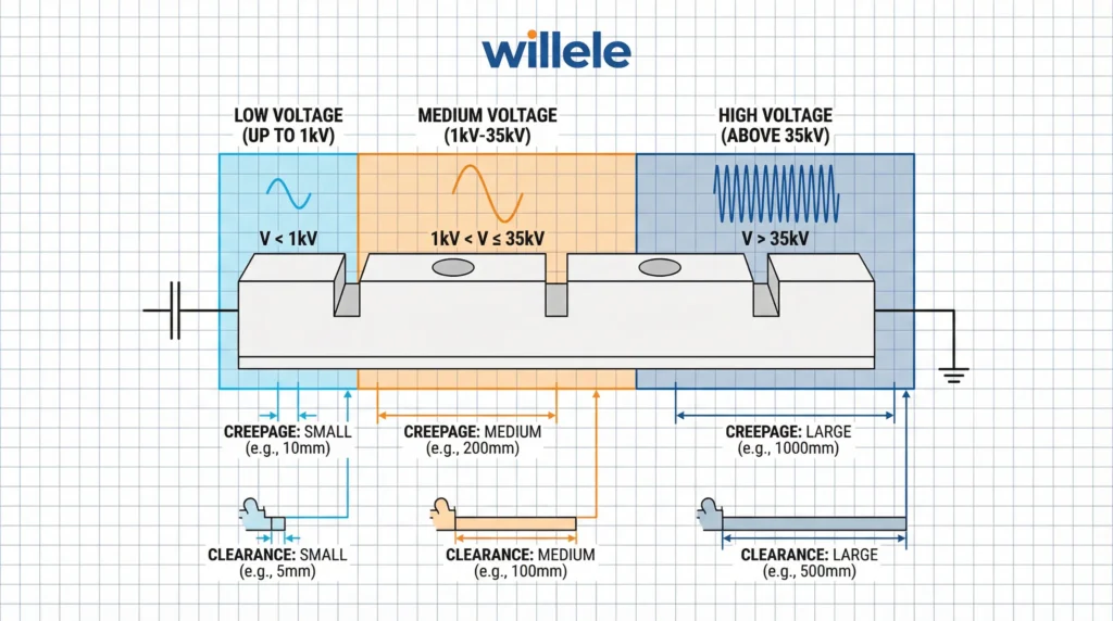
Busbar insulators are classified into distinct voltage categories, each with specific design requirements and testing protocols:
| Voltage Class | Voltage Range | Typical Applications | Key Requirements |
|---|---|---|---|
| Low Voltage (LV) | Up to 1,000V AC / 1,500V DC | Industrial control panels, motor control centers, building distribution | Basic insulation, flame resistance, mechanical strength |
| Medium Voltage (MV) | 1kV to 35kV | Switchgear, substations, industrial distribution | Enhanced creepage/clearance, tracking resistance, impulse withstand |
| High Voltage (HV) | 35kV to 230kV | Utility substations, transmission systems | Superior dielectric properties, environmental resistance, extended creepage |
| Extra High Voltage (EHV) | Above 230kV | Major transmission infrastructure | Advanced materials, specialized designs, rigorous testing |
Detailed Voltage Rating Specifications
The table below provides comprehensive specifications for common busbar insulator voltage ratings:
| Rated Voltage | Minimum Creepage Distance | Minimum Clearance | Impulse Withstand (BIL) | Power Frequency Test Voltage | Typical CTI Rating |
|---|---|---|---|---|---|
| 690V AC | 10mm | 6mm | 8kV | 3.5kV | ≥175 (CTI III) |
| 1,000V AC | 16mm | 10mm | 12kV | 6kV | ≥175 (CTI III) |
| 12kV | 160mm | 95mm | 95kV | 42kV | ≥250 (CTI II) |
| 24kV | 320mm | 190mm | 150kV | 70kV | ≥250 (CTI II) |
| 36kV | 480mm | 290mm | 200kV | 95kV | ≥250 (CTI II) |
CTI = Comparative Tracking Index, a measure of material resistance to electrical tracking
Key Factors Affecting Voltage Ratings
Creepage Distance
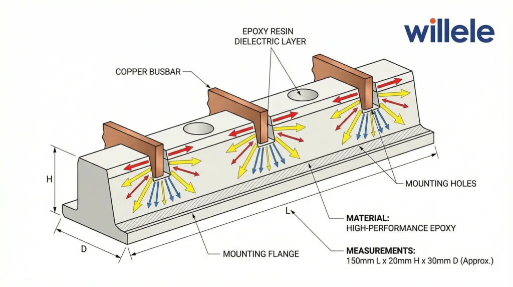
Creepage distance refers to the shortest path along the insulator surface between conductive parts. This parameter is critical because surface contamination, moisture, and environmental factors can create conductive paths along the insulator exterior. Understanding voltage ratings for busbar insulators requires careful attention to creepage distance requirements, which increase with:
- Higher operating voltages
- More severe pollution environments
- Outdoor or coastal installations
- Industrial atmospheres with conductive dust
Clearance Distance
Clearance represents the shortest distance through air between conductive elements. Unlike creepage, clearance focuses on dielectric breakdown through the air gap. Adequate clearance prevents:
- Electrical arcing and flashover
- Corona discharge at high voltages
- Voltage stress concentration
- Transient overvoltage breakdown
Material Properties and Dielectric Strength
The insulating material’s inherent properties fundamentally determine voltage rating capabilities. Common materials used in busbar insulators include:
| Material | Dielectric Strength (kV/mm) | Tracking Resistance (CTI) | Temperature Range (°C) | Key Advantages | Typical Voltage Applications |
|---|---|---|---|---|---|
| DMC (Dough Molding Compound) | 15-20 | 175-250 | -40 to +140 | Cost-effective, good mechanical properties | LV to 12kV |
| BMC (Bulk Molding Compound) | 18-22 | 200-300 | -40 to +150 | Excellent tracking resistance, dimensional stability | LV to 24kV |
| Epoxy Resin | 20-30 | 250-400 | -40 to +155 | Superior electrical properties, moisture resistance | LV to 36kV |
| Polyester Resin | 16-20 | 175-250 | -40 to +130 | Good chemical resistance, economical | LV applications |
| Silicone | 18-25 | 600+ | -60 to +200 | Hydrophobic, excellent pollution performance | MV to HV outdoor |
| Porcelain | 25-35 | N/A | -50 to +200 | Traditional material, proven reliability | All voltage classes |
Environmental Factors
Environmental conditions significantly impact voltage rating effectiveness:
- Pollution: Conductive contaminants reduce surface resistance and effective creepage distance
- Humidity: Moisture absorption can reduce dielectric strength and create surface conductivity
- Temperature: Extreme temperatures affect material properties and thermal expansion
- Altitude: Reduced air density at high elevations decreases dielectric strength, requiring voltage derating
- UV exposure: Outdoor installations require UV-resistant materials to prevent degradation
International Standards and Compliance
Understanding voltage ratings for busbar insulators requires familiarity with applicable international standards that define testing protocols, rating methodologies, and safety requirements.
Key Standards Organizations
IEC (International Electrotechnical Commission)
- IEC 61109: Composite insulators for AC overhead lines with a nominal voltage greater than 1000 V
- IEC 60694: Common specifications for high-voltage switchgear and controlgear standards
- IEC 60071: Insulation co-ordination
- IEC 60529: Degrees of protection provided by enclosures (IP Code)
UL (Underwriters Laboratories)
- UL 1449: Surge protective devices
- UL 508: Industrial control equipment
- UL 891: Switchboards
IEEE (Institute of Electrical and Electronics Engineers)
- IEEE C37.20.1: Metal-enclosed low-voltage power circuit breaker switchgear
- IEEE C37.20.2: Metal-clad switchgear
ANSI (American National Standards Institute)
- ANSI C29: Test methods for electrical power insulators
Voltage Rating Testing and Verification
Manufacturers must conduct rigorous testing to verify voltage ratings:
- Power frequency withstand test: Application of test voltage for specified duration (typically 60 seconds)
- Impulse voltage test: Simulation of lightning and switching surges
- Partial discharge test: Detection of internal defects and voids
- Tracking and erosion test: Assessment of surface degradation resistance
- Environmental conditioning: Temperature cycling, humidity exposure, pollution testing
Voltage Class Comparison for Application Selection
When selecting busbar insulators, engineers must match voltage ratings to system requirements while considering safety margins and environmental factors:
| Selection Criteria | Low Voltage (≤1kV) | Medium Voltage (1-35kV) | High Voltage (>35kV) |
|---|---|---|---|
| Primary Safety Factor | 2.0-2.5× rated voltage | 1.5-2.0× rated voltage | 1.3-1.5× rated voltage |
| Creepage Distance Priority | Moderate | High | Critical |
| Material Cost Impact | Low | Medium | High |
| Testing Complexity | Basic | Comprehensive | Extensive |
| Installation Complexity | Simple | Moderate | Complex |
| Maintenance Requirements | Minimal | Regular inspection | Rigorous maintenance program |
| Environmental Sensitivity | Low | Medium | High |
| Typical Safety Margin | 50-150% | 30-100% | 20-50% |
Practical Selection Criteria
Step-by-Step Selection Process
- Determine system voltage: Identify nominal voltage and maximum operating voltage
- Assess environment: Evaluate pollution level, humidity, temperature extremes, altitude
- Calculate required creepage: Apply pollution severity factors per IEC 60815
- Verify clearance requirements: Ensure adequate air gap per applicable standards
- Select appropriate material: Match material properties to environmental conditions
- Confirm mechanical requirements: Ensure adequate short-circuit and mechanical strength
- Verify compliance: Check certifications and test reports against applicable standards
Common Application Scenarios
Industrial Control Panels (480V-690V)
- Standard DMC or BMC insulators
- CTI rating ≥175
- Creepage distance 10-16mm
- IP20 or IP40 enclosure rating
Medium Voltage Switchgear (12kV-24kV)
- Epoxy or BMC insulators
- CTI rating ≥250
- Creepage distance 160-320mm
- Indoor installation with controlled environment
Outdoor Substations (36kV+)
- Silicone or porcelain insulators
- Enhanced pollution performance
- Creepage distance >480mm
- UV resistance and hydrophobic properties
Frequently Asked Questions
Q: How do I determine the correct voltage rating for my application?
A: Start with your system’s maximum operating voltage and apply appropriate safety factors (typically 1.5-2.5× depending on voltage class). Consider environmental conditions, applicable standards, and transient overvoltage possibilities. Consult manufacturer specifications and engineering guidelines for your specific application.
Q: What is the difference between rated voltage and withstand voltage?
A: Rated voltage is the maximum continuous operating voltage the insulator can handle. Withstand voltage (both power frequency and impulse) represents the higher voltage levels the insulator can endure during testing or transient events without failure. Withstand voltages are typically several times higher than rated voltage.
Q: How does pollution affect voltage ratings?
A: Pollution deposits on insulator surfaces create conductive paths that effectively reduce creepage distance. Heavy pollution can reduce the insulator’s voltage withstand capability by 50% or more. This is addressed by selecting insulators with increased creepage distance based on pollution severity levels defined in IEC 60815.
Q: Can I use a higher voltage-rated insulator than required?
A: Yes, using insulators with higher voltage ratings than required provides additional safety margin and is common practice. However, consider physical size constraints and cost factors. The additional safety margin is particularly valuable in harsh environments or critical applications.
Q: Do voltage ratings change with altitude?
A: Yes, the dielectric strength of air decreases with altitude due to reduced air density. At elevations above 1,000 meters, voltage ratings must be derated. The correction factor is approximately 1.25% per 100 meters above 1,000 meters. High-altitude installations require special consideration.
