Using MRK Terminal Blocks in PLC Systems: Connection Guide for Automation
Modern industrial automation relies on precise, reliable electrical connections to ensure seamless communication between programmable logic controllers (PLCs) and field devices. At the heart of these connections lies a critical component often overlooked: the MRK terminal block. These modular connectors serve as the bridge between control systems and the physical world, handling everything from sensor signals to actuator commands with unwavering consistency.
MRK terminal blocks have earned their reputation in automation environments through a combination of robust construction, standardized mounting, and versatile configuration options. Whether you’re designing a new control panel or retrofitting an existing system, understanding how to properly select, install, and maintain these terminal blocks can mean the difference between a system that runs flawlessly for years and one plagued by intermittent faults and costly downtime.
Understanding MRK Terminal Blocks in Industrial Automation
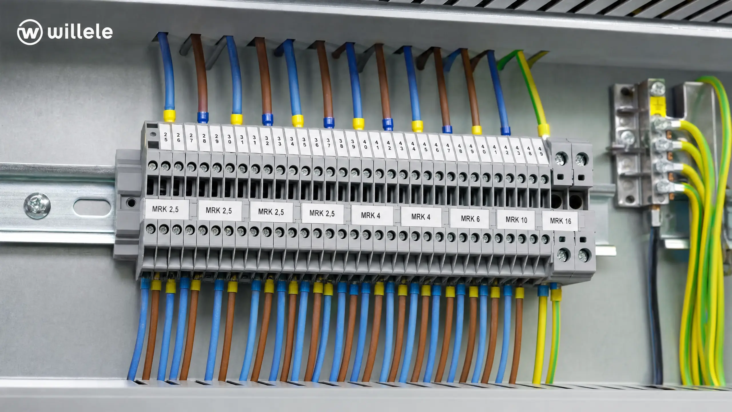
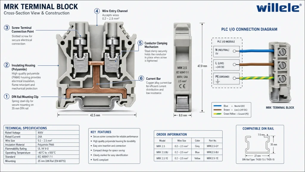
MRK terminal blocks represent a specific category of DIN rail-mounted connectors designed for industrial control applications. The designation “MRK” typically refers to screw-connection rail terminal blocks with standardized dimensions and mounting specifications that comply with international electrical standards. These blocks feature a modular design that allows them to be arranged side-by-side on standard 35mm DIN rails, creating organized terminal strips that can accommodate dozens of connections in a compact footprint.
The construction of MRK terminal blocks prioritizes both safety and functionality. The insulating housing, typically manufactured from high-grade polyamide (PA) or similar thermoplastic materials, provides electrical isolation between adjacent terminals while withstanding the temperature extremes common in industrial environments. Inside this housing, brass or copper alloy conductor bars ensure low-resistance current paths, while hardened steel screws deliver consistent clamping force across a wide range of wire gauges.
What sets MRK terminal blocks apart in PLC applications is their systematic approach to signal organization. Unlike general-purpose terminal strips, these blocks are engineered with automation requirements in mind: consistent spacing for dense wiring, clear marking areas for circuit identification, and compatibility with standard labeling systems that help technicians trace signals quickly during commissioning or troubleshooting.
Key Specifications and Technical Parameters
Selecting the appropriate MRK terminal block for your PLC system requires careful attention to several critical specifications. The wire gauge capacity stands as the primary consideration, with most MRK blocks accommodating conductors ranging from 0.2mm² to 4mm² (approximately 24 AWG to 12 AWG). Common variants include the MRK 2.5 for general-purpose applications handling up to 2.5mm² conductors, and the MRK 4 for higher-current circuits requiring 4mm² wire capacity.
Voltage and current ratings define the operational envelope within which these terminal blocks can safely function. Standard MRK terminal blocks typically carry voltage ratings of 500V to 800V AC, with current capacities ranging from 17A to 32A depending on the conductor cross-section and ambient temperature. These ratings incorporate safety margins that account for continuous operation under typical industrial conditions, but designers must verify that actual operating parameters remain well within these limits to ensure long-term reliability.
The physical dimensions of MRK terminal blocks follow standardized patterns that facilitate panel layout and component selection. Most blocks measure between 5mm and 8mm in width per position, allowing high-density installations where panel space comes at a premium. The terminal height typically ranges from 40mm to 50mm, providing adequate clearance for wire bending radius while maintaining a low profile that conserves vertical space within control cabinets.
| Specification | MRK 2.5 | MRK 4 | MRK 6 |
|---|---|---|---|
| Wire Capacity | 0.2-2.5mm² | 0.2-4mm² | 0.5-6mm² |
| AWG Range | 24-14 | 24-12 | 20-10 |
| Rated Current | 17A | 24A | 32A |
| Rated Voltage | 500V AC | 630V AC | 800V AC |
| Terminal Width | 5.2mm | 6.2mm | 8.2mm |
| Screw Type | M3 | M3.5 | M4 |
| Torque Spec | 0.5 Nm | 0.8 Nm | 1.2 Nm |
Temperature performance represents another crucial specification, particularly in environments subject to extreme conditions. MRK terminal blocks typically operate reliably across a temperature range of -40°C to +100°C, though sustained operation at temperature extremes may require derating of current capacity. The insulating materials maintain their dielectric properties throughout this range, preventing breakdown or tracking that could compromise system safety.
PLC I/O Connection Architecture
The connection architecture between PLCs and field devices through MRK terminal blocks follows established patterns that balance accessibility, maintainability, and signal integrity. In a typical configuration, the PLC’s input and output modules connect to dedicated terminal block strips positioned adjacent to the controller. This arrangement creates a clear demarcation point where internal panel wiring meets external field cables, simplifying troubleshooting and reducing the risk of damage to expensive PLC hardware during maintenance activities.
For digital input circuits, MRK terminal blocks facilitate the connection of sensors, limit switches, and other discrete devices to the PLC’s input cards. The standard practice involves dedicating separate terminal positions for signal wires and common returns, with jumper bars linking multiple common terminals to create shared reference points. This topology minimizes wiring complexity while maintaining the ability to isolate individual circuits when necessary. Modern installations often incorporate fused terminal blocks at strategic points to protect input circuits from overcurrent conditions without requiring individual circuit breakers.
Output circuits present different challenges, as they must handle higher currents and potentially inductive loads that generate voltage spikes during switching. MRK terminal blocks serving PLC outputs typically feature more robust conductor bars and higher current ratings to accommodate relay coils, solenoid valves, and indicator lamps. Many designers prefer to interpose relay terminal blocks between the PLC outputs and final loads, using the PLC to switch low-current control relays that in turn handle the heavier field loads. This approach extends PLC output life and provides additional isolation between control and power circuits.
Analog signal connections demand particular attention to terminal block selection and wiring practices. While MRK terminal blocks can certainly handle analog signals, the low voltage levels and susceptibility to electrical noise require careful consideration. Shielded cable termination becomes critical, with the shield typically grounded at one end through a dedicated terminal position. Some installations benefit from specialized terminal blocks that incorporate built-in shield termination points, ensuring consistent grounding practices across the entire panel.
Installation Best Practices and Wiring Techniques
Proper installation of MRK terminal blocks begins long before the first wire gets terminated. The DIN rail must be securely mounted to the panel backplate with adequate spacing from other components to allow comfortable access for wiring and maintenance. Standard practice calls for mounting terminal strips in horizontal rows, with input terminals grouped separately from outputs and power distribution terminals isolated from signal-level connections. This organization reduces the likelihood of wiring errors and makes circuit tracing more intuitive for technicians unfamiliar with the specific installation.
Wire preparation significantly impacts connection reliability and long-term performance. Conductors should be stripped to expose just enough bare wire to reach the terminal’s clamping point without leaving excess exposed metal that could contact adjacent terminals. For stranded wire, ferrules provide the ideal termination method, compressing multiple strands into a solid, cylindrical form that seats consistently in the terminal screw mechanism. The ferrule prevents individual strands from splaying during insertion and eliminates the risk of stray strands creating short circuits.
Torque control during terminal screw tightening cannot be overstated. Under-tightened connections exhibit high resistance that generates heat and may eventually fail due to oxidation or mechanical vibration. Over-tightening damages the wire conductor, potentially breaking strands or deforming solid wire in ways that reduce current-carrying capacity and create stress points where fatigue failures can occur. Quality installations employ torque screwdrivers calibrated to the manufacturer’s specifications, typically ranging from 0.5 Nm for smaller MRK 2.5 blocks to 1.2 Nm for larger MRK 6 variants.
The physical routing of wires to and from terminal blocks deserves careful planning. Wires should approach terminals in organized bundles, secured with cable ties at regular intervals to prevent sagging and maintain a professional appearance. Sharp bends must be avoided, as they can damage conductor insulation and create stress concentrations that lead to premature failure. Many experienced panel builders maintain a minimum bend radius of ten times the cable diameter, ensuring that wires curve gently even in space-constrained installations.
Common Connection Configurations
Several standard connection patterns appear repeatedly in PLC systems using MRK terminal blocks, each optimized for specific signal types and operational requirements. The single feed-through configuration represents the simplest arrangement, where one wire enters the terminal block and another exits, with the internal conductor bar creating the electrical connection. This topology suits point-to-point wiring where each signal requires individual routing without shared commons or distribution to multiple destinations.
Multi-level terminal blocks expand the basic feed-through concept by stacking two or three independent conductor levels within a single terminal position. This design dramatically increases wiring density, allowing three separate circuits to occupy the same DIN rail footprint as a single conventional terminal. In PLC applications, multi-level blocks often separate signal, common, and ground connections into distinct layers, reducing the risk of miswiring while maintaining clear circuit organization. The trade-off comes in reduced accessibility for troubleshooting, as probing the middle or bottom level requires careful maneuvering around wires connected to upper levels.
Distribution terminal blocks incorporate internal jumpers or bus bars that connect multiple terminal positions together, creating common points for power distribution or signal reference. These blocks prove invaluable for PLC input circuits where numerous sensors share a common 24V DC supply or ground reference. Rather than running individual wires from each sensor back to a central power terminal, the distribution block allows a single supply wire to feed an entire row of terminals, with each position providing a tap point for individual sensor connections.
| Configuration Type | Typical Application | Advantages | Considerations |
|---|---|---|---|
| Single Feed-Through | Point-to-point I/O | Simple, easy to trace | Requires more rail space |
| Multi-Level | Dense signal wiring | Space-efficient | Harder to probe/troubleshoot |
| Distribution/Jumper | Common power/ground | Reduces wire count | Requires careful load calculation |
| Fused Terminal | Output protection | Individual circuit protection | Higher cost per position |
| Disconnect Terminal | Maintenance isolation | Safe circuit interruption | Adds complexity to panel |
Fused terminal blocks integrate overcurrent protection directly into the terminal structure, positioning a small cartridge fuse in series with the connection point. This configuration provides individual circuit protection without the bulk and expense of separate fuse holders or circuit breakers. PLC output circuits benefit particularly from this arrangement, as fuses can be sized to protect both the PLC output module and the field wiring from fault conditions. When a fault occurs, the affected circuit opens immediately while adjacent circuits continue operating normally, simplifying diagnosis and minimizing system downtime.
Troubleshooting and Maintenance Strategies
Effective troubleshooting of MRK terminal block connections begins with systematic visual inspection. Loose terminal screws often reveal themselves through discolored insulation near the connection point, a telltale sign of resistive heating. Technicians should verify that all screws are properly tightened to specification, paying particular attention to terminals that carry higher currents or experience frequent vibration. A loose connection may function intermittently, creating frustrating problems that appear and disappear without obvious cause.
Continuity testing with a digital multimeter provides definitive evidence of connection integrity. With power removed from the circuit, technicians can verify that current paths exist where expected and that no unwanted connections bridge adjacent terminals. This testing proves especially valuable after initial installation or following modifications to existing wiring, catching errors before energizing the system and potentially damaging expensive components. For active troubleshooting with power applied, voltage measurements at terminal points quickly isolate whether problems originate upstream in the field wiring or downstream in the PLC or load devices.
Thermal imaging has emerged as a powerful diagnostic tool for terminal block maintenance. Infrared cameras reveal hot spots that indicate high-resistance connections long before they progress to complete failure. Regular thermal surveys of control panels, conducted during normal operation under typical load conditions, allow maintenance teams to identify and address developing problems during planned downtime rather than responding to unexpected failures. Connections that measure more than 10°C above ambient temperature warrant investigation, while those exceeding 20°C above ambient require immediate attention.
Environmental factors significantly influence terminal block longevity and reliability. Dust accumulation on terminal strips creates moisture-absorbing deposits that can lead to tracking between adjacent terminals, particularly in high-voltage applications. Periodic cleaning with compressed air or vacuum systems removes these contaminants before they compromise insulation. In harsh environments subject to corrosive atmospheres, terminal blocks with enhanced sealing or conformal coatings provide additional protection, though these specialized variants command premium pricing.
The practice of preventive maintenance extends terminal block service life and reduces unexpected failures. Annual or biannual inspections should include retorquing terminal screws, as thermal cycling and vibration can gradually loosen connections over time. Documentation of terminal assignments and circuit functions proves invaluable during these inspections, allowing technicians to verify that the physical installation matches the design intent and that no unauthorized modifications have introduced potential problems.
Integration with Modern Automation Standards
Contemporary automation systems increasingly demand terminal blocks that support not just basic electrical connections but also integration with digital communication protocols and smart monitoring capabilities. While traditional MRK terminal blocks excel at their core function of wire termination, the evolution toward Industry 4.0 and IIoT-enabled factories has spawned enhanced variants that bridge the gap between conventional wiring and networked automation.
Intelligent terminal blocks incorporate embedded electronics that monitor connection status, current flow, and temperature in real-time. These devices communicate with PLCs or dedicated monitoring systems via industrial protocols such as IO-Link, providing diagnostic data that enables predictive maintenance strategies. When a connection begins to degrade, the system alerts maintenance personnel before complete failure occurs, allowing intervention during scheduled downtime rather than in response to production-stopping faults.
The push toward modular, reconfigurable automation systems has influenced terminal block design as well. Quick-connect terminal blocks using spring-clamp or push-in technology eliminate the need for screwdrivers during installation and modification, dramatically reducing the time required to wire or rewire control panels. While screw-type MRK terminal blocks remain the standard for permanent installations, these tool-free alternatives gain traction in applications where frequent reconfiguration is anticipated or where installation speed justifies the higher component cost.
Standardization efforts across the automation industry have established common terminal block footprints and mounting dimensions that facilitate multi-vendor integration. A control panel designed around standard MRK terminal blocks can accommodate components from various manufacturers without requiring custom mounting solutions or adapter hardware. This interoperability reduces procurement complexity and provides flexibility in component sourcing, important considerations for global manufacturers managing supply chains across multiple regions.
Selecting MRK Terminal Blocks for Your Application
The selection process for MRK terminal blocks should begin with a comprehensive assessment of electrical requirements. Calculate the maximum current each circuit will carry under normal and fault conditions, then select terminal blocks rated for at least 125% of this value to provide adequate safety margin. Voltage ratings must exceed the highest potential that could appear across the terminal under any operating scenario, including transient overvoltages from inductive load switching or lightning-induced surges.
Wire gauge compatibility ranks as the second critical selection criterion. The terminal block must accommodate the smallest and largest wire sizes present in your application, with sufficient clamping force to secure fine-gauge signal wires while providing adequate current capacity for larger power conductors. Many designers standardize on one or two wire gauges throughout a panel to simplify inventory and reduce the likelihood of selecting incorrect wire during installation or maintenance.
Physical space constraints often dictate terminal block selection in retrofit applications or compact panel designs. Calculate the total number of terminal positions required, including spares for future expansion, then determine whether standard single-level blocks will fit within available DIN rail space. If not, multi-level blocks or higher-density alternatives may be necessary, though these choices come with trade-offs in accessibility and ease of troubleshooting.
Special features warrant consideration based on application-specific needs. Fused terminal blocks add circuit protection at modest cost increases. Disconnect terminal blocks provide convenient isolation points for maintenance without requiring wire removal. Ground terminal blocks with enhanced contact area ensure reliable protective earth connections. LED-equipped terminal blocks offer visual indication of circuit status without requiring separate indicator lamps. Each feature adds value in appropriate contexts but also increases cost and complexity, requiring careful evaluation of whether the benefits justify the investment.
Comparison: MRK Terminal Blocks vs. Alternative Connection Methods
| Feature | MRK Terminal Blocks | Spring-Clamp Terminals | Pluggable Connectors | Direct PLC Wiring |
|---|---|---|---|---|
| Installation Speed | Moderate | Fast | Very Fast | Slow |
| Connection Reliability | Excellent | Excellent | Good | Excellent |
| Maintenance Access | Good | Very Good | Fair | Poor |
| Vibration Resistance | Very Good | Excellent | Good | Very Good |
| Cost per Connection | Low | Moderate | High | Very Low |
| Reconfiguration Ease | Moderate | Easy | Very Easy | Difficult |
| Industry Acceptance | Universal | Growing | Specialized | Declining |
The comparison reveals that MRK terminal blocks occupy a sweet spot in the automation connectivity landscape, balancing cost, reliability, and maintainability in ways that alternative methods struggle to match. While direct wiring to PLC terminals minimizes component cost, it sacrifices accessibility and makes future modifications unnecessarily difficult. Pluggable connectors offer unmatched reconfiguration speed but at premium prices that few projects can justify except in specialized applications requiring frequent changes.
Frequently Asked Questions
Q: What is the difference between MRK terminal blocks and standard terminal blocks?
A: MRK terminal blocks specifically refer to screw-connection rail-mounted terminal blocks designed for industrial automation applications. They feature standardized dimensions for DIN rail mounting, consistent spacing for high-density installations, and specifications optimized for PLC I/O connections. Standard terminal blocks may lack these automation-specific features and dimensional consistency.
Q: Can I connect two wires to a single MRK terminal position?
A: This depends on the specific terminal block model and manufacturer specifications. Some MRK terminal blocks explicitly permit dual-wire connections up to certain combined cross-sections, while others are designed for single-wire termination only. Always consult the manufacturer’s datasheet to verify whether dual-wire connections are approved, as improper connections can lead to loose contacts and potential failures.
Q: How often should I retorque MRK terminal block screws?
A: Industry best practice recommends retorquing terminal screws annually in stable environments, or every six months in applications subject to significant vibration or thermal cycling. Initial retorquing after the first 30-90 days of operation is also advisable, as new connections may settle during the break-in period.
Q: What wire preparation method works best with MRK terminal blocks?
A: For stranded wire, ferrules (wire end sleeves) provide the most reliable connection by consolidating multiple strands into a solid termination that won’t splay or loosen over time. Solid wire can be terminated directly without ferrules. Always strip wire to the minimum length necessary to reach the clamping point, typically 8-10mm for most MRK terminal blocks.
Q: Are MRK terminal blocks suitable for analog signals in PLC systems?
A: Yes, MRK terminal blocks can handle analog signals, but proper installation practices become critical. Use shielded cable for analog connections, terminate shields properly at one end through dedicated ground terminals, and maintain physical separation between analog signal terminals and high-current or switching circuits to minimize electrical noise interference.
Q: What temperature rating should I specify for harsh industrial environments?
A: Standard MRK terminal blocks typically operate reliably from -40°C to +100°C, which suffices for most industrial applications. For extreme environments, specify terminal blocks with enhanced temperature ratings or environmental protection (IP20 or higher). Remember that current capacity may require derating at elevated ambient temperatures.
