
WHAT IS BUSBAR INSULATOR

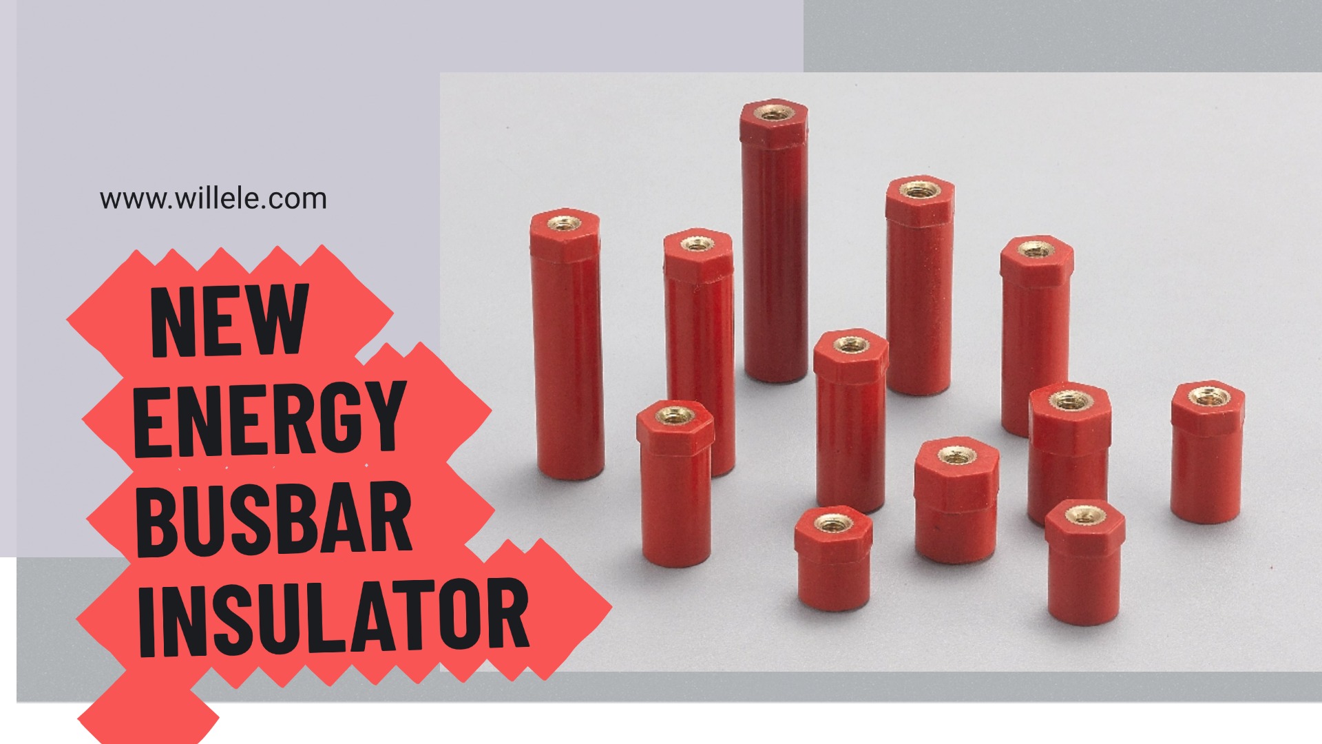
WHAT IS BUSBAR INSULATOR
Introduction
What is a busbar insulator ? In the intricate architecture of modern power distribution, system reliability and safety are determined not by the capacity of the conductors alone, but by the performance of specialized, often unseen, components. Among these critical elements, the BUSBAR INSULATOR stands as a fundamental, non-negotiable requirement for operational safety, electrical efficiency, and long-term system longevity.1
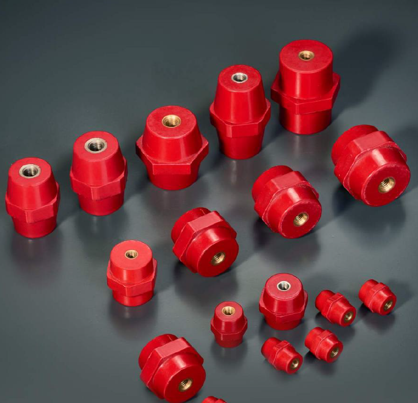
A busbar insulator is an engineered component—typically cylindrical or conical—designed to serve simultaneously as an electrical buffer and a robust mechanical anchor for busbars, which are metallic strips, usually copper or aluminum, conveying high electrical currents within complex enclosures, switchgear, and panel boards.1 Its function transcends simple insulation; it is the structural link that ensures conductors remain isolated from grounded structures, thereby preventing catastrophic electrical failure in high-current environments.1
For electrical engineers, system integrators, and facility managers, the correct selection of a busbar insulator is recognized as a strategic, long-term investment in operational safety and minimized maintenance, rather than a minor specification detail.1 This comprehensive guide analyzes the core functions, material science, stringent regulatory compliance requirements, and failure mitigation strategies necessary for optimizing busbar insulator selection in demanding electrical environments.
I. The Foundation of Power Reliability: Defining the Busbar Insulator
The critical role of the busbar insulator is defined by a multifaceted responsibility in system performance, extending its influence across electrical safety, mechanical endurance, environmental protection, and overall system design efficiency.1
H2: 1.1 Beyond Isolation: The Core Functions of a Busbar Insulator
Electrical Isolation (The Primary Safety Barrier)
The paramount function of the busbar insulator is the prevention of unintended current flow. It ensures the energized busbar remains electrically separated from its supporting structure or enclosure.1 This function is foundational to mitigating short circuits, minimizing the risk of electrical fires, and is critically important in high-voltage environments where the potential for electrical arcing is elevated.1 By acting as a primary safety barrier, the insulator protects both personnel and equipment from dangerous electrical faults.4
Mechanical Support and Structural Integrity
Busbars operate under conditions that impose significant dynamic forces, including constant system vibrations, cyclic thermal expansion and contraction (due to load fluctuations), and intense electromagnetic stress during potential fault conditions.1 The insulator must securely hold the busbar in precise, predefined alignment.1 This secure anchoring is necessary to maintain system stability and integrity throughout normal operations and to withstand severe short-circuit forces.4
The interdependence between the mechanical function and the electrical integrity of the component is critical. The long-term dielectric performance of the insulator is inextricably linked to its mechanical stability. If improper installation techniques are used, such as applying improper torque settings, or if the insulator is subject to sustained mechanical stresses, cracking or fracturing can occur.7 A mechanical breach compromises the component’s integrity, allowing contaminants like moisture and dust to enter.1 This ingress immediately accelerates the degradation of electrical performance, leading directly to tracking and catastrophic electrical failure.7 Therefore, achieving the required long-term dielectric performance necessitates rigorous adherence to mechanical stress tolerances during both design and installation.
Environmental Protection and Longevity
Insulators provide a critical shield, protecting the conductor path itself from external environmental stressors.1 These stressors include moisture, airborne dust, chemical exposure, and damaging UV radiation.7 Contaminants are known to cause corrosion and surface degradation over time, which directly compromises system efficiency and safety.1 By maintaining a pristine electrical path, insulators significantly extend the operational lifespan of the entire electrical system.1
Enhancing System Efficiency and Design Footprint
In modern, high-density distribution systems, space optimization is paramount. High-performance busbar insulation allows system designers to reduce the required clearance and creepage distance between conductors and grounded surfaces.1 This capability minimizes the overall circuit footprint, leading to smaller, more compact switchgear enclosures.1
This enhancement in design efficiency is closely linked to regulatory compliance. The utilization of robust, Solid-Insulated Systems (SIS) technology is crucial for achieving the necessary space reduction while simultaneously satisfying stringent dielectric test requirements mandated by standards like IEC 61439 or ANSI/IEEE C37.20.10 The high dielectric strength of modern insulation systems enables high-density designs that meet strict compliance standards, effectively making high-performance insulation technology a critical enabler for modern, compact power distribution architectures. Furthermore, busbar insulators contribute to improved operational quality by dampening electromagnetic vibrations, thereby reducing audible noise (the characteristic humming or buzzing) and ensuring energy is efficiently contained within the system.1
II. Classification and Architecture: Matching Insulators to Application Needs
The process of selecting the correct busbar insulator demands a rigorous classification based on the physical role, the operating environment, and the material’s ability to withstand thermal and electrical demands.1
H2: 2.1 Functional Forms: Choosing the Right Mechanical Role
Busbar insulators are engineered into distinct functional forms tailored to meet the specific mechanical requirements of the power distribution architecture.14
| Type | Primary Function | Mechanical Stress Handled | Typical Application Environment |
| Support Insulator | Mechanical stability and electrical isolation | Standard vibration and static load | Standard switchgear, control gear assemblies 1 |
| Standoff Insulator | Maintaining fixed air clearance and isolation | Compression and static load | Secure mounting requiring precise air gaps 1 |
| Bushing Insulator | Conductor penetration through grounded barriers | Compression and shear loads | Transformer casings, circuit breaker enclosures 1 |
| Strain Insulator | Handling high mechanical tension | Tensile stress and long-span loads | Overhead power systems, bends, and curves 1 |
Support Insulators and Standoff Insulators
Support insulators represent the most common type, providing core mechanical stability and electrical isolation within switchgear and distribution assemblies.1 Standoff insulators, a specialized subset, are specifically engineered to maintain a precise, consistent, fixed distance between the energized busbar and the mounting surface or enclosure.1 This fixed air gap is vital for guaranteeing the specified electrical clearances required by regulatory codes.1
Bushing Insulators and Strain Insulators
Bushing insulators fulfill the critical function of allowing a conductor to safely pass through a grounded barrier, such as the wall of a transformer casing or a circuit breaker enclosure, while ensuring continuous high-integrity insulation.1 Strain insulators, conversely, are typically employed in overhead power systems or long spans. They are structurally designed to handle significant mechanical tension and stress, often being utilized at curves, corners, or points where the conductor direction changes.1
H2: 2.2 Material Science Deep Dive: Thermal, Electrical, and Chemical Resilience
The material chosen for the busbar insulator defines its resistance profile against heat, mechanical stress, chemical exposure, and dielectric breakdown.1
Epoxy Resins and Bulk Molding Compound (BMC)
Epoxy resins are valued for their lightweight, compact nature, robust electrical insulation, and strong mechanical strength. They offer high corrosion and chemical resistance and are typically used in indoor, low to medium-voltage systems.1 Bulk Molding Compound (BMC) is a composite material utilizing a thermosetting resin reinforced with glass fibers.3 BMC is a high-strength, cost-effective solution widely used in low-voltage applications (660V to 4500V).1 Standard BMC provides robust heat resistance, often rated up to Class B (130°C) or 140°C, which is necessary for managing operational thermal loads within switchgear.1
Crucially, materials such as BMC and epoxy resin exhibit low thermal conductivity.16 This property enables them to function as effective thermal barriers, minimizing the transfer of excessive heat—generated by busbar overloading or high-resistance joints—to surrounding components.16 In industrial low-voltage systems prone to current spikes, specifying an insulator with inherent thermal management capabilities (like BMC) ensures greater system stability during transient or peak usage.
Polymer Composites and Porcelain
Polymer composites are lightweight, versatile materials offering exceptional resistance to external environmental factors, particularly UV radiation, moisture, and pollution.1 Their chemical resistance makes them the preferred modern choice for pollution-prone industrial zones, humid coastal regions (due to resistance to salt spray corrosion), and outdoor applications where weight and ease of installation are primary concerns.8
Porcelain, or ceramic, is the traditional choice, known for its superb insulation qualities, high mechanical strength, and ability to tolerate extreme temperatures, often up to 1000°C.1 Porcelain is typically specified for high-voltage and outdoor substations where superior dielectric strength and weather resilience are required.1
A significant shift in material specification for high-voltage applications is evident in challenging environments. While porcelain offers excellent temperature tolerance, it suffers from poor impact resistance, is heavy, and difficult to install.12 Polymer composites, conversely, offer excellent resistance to surface tracking, superior impact resistance, and are significantly lighter.12 In modern engineering specifications for environments subject to heavy industrial pollution or corrosive coastal conditions, polymer composites are often favored over porcelain. The investment in polymer technology provides substantial long-term benefits in terms of safer, easier installation and a reduced maintenance burden due to superior tracking resistance over the lifetime of the system.12
| Material | Typical Voltage Range | Key Strengths | Environmental Suitability | Installation/Impact |
| Epoxy Resin | Low to Medium | High dielectric strength, compact, low corrosion risk | Indoor, industrial settings 13 | Lightweight, easy |
| BMC/DMC | Low (660V–4500V) | Cost-effective, high mechanical strength (up to 1500 LBS) 1 | Standard industrial, moderate heat (up to 140°C) 1 | Good impact resistance |
| Polymer Composites | Medium to High | UV resistance, tracking resistance, high impact strength | Outdoor, pollution-prone, coastal environments 12 | Lightweight, easy |
| Porcelain/Ceramic | High Voltage (>100kV) | Exceptional dielectric strength, extreme temperature resistance 1 | Outdoor substations, harsh weather exposure 13 | Heavy, brittle (Poor impact) 12 |
H2: 2.3 Voltage Specifications and Design Complexity
The required operational voltage of an electrical system fundamentally dictates the design complexity and material requirements of the busbar insulator.1
Low Voltage (LV) Systems (660V–4500V)
Insulators designed for low-voltage applications are generally simpler and smaller. They are frequently constructed from BMC or Sheet Molding Compound (SMC) due to the necessity for strong mechanical support, often requiring tensile strengths up to 1500 LBS, coupled with cost-effectiveness.1
High Voltage (HV) Systems (Exceeding 100kV)
High-voltage insulators require construction from highly robust materials, typically ceramics or advanced composites.1 The design complexity increases substantially to manage the high potential for electrical arcing and surface leakage. HV insulators feature specialized geometries, including multiple sheds or discs, which serve to significantly increase the surface area and lengthen the creepage distance. This extended path is critical for preventing electrical flashover and maintaining dielectric integrity in demanding, high-potential environments.1
III. Manufacturing and Installation: Insulating Busbar Methods
Beyond the selection of the mechanical support component, the method used to insulate the busbar conductor itself is crucial, defining the system’s thermal, mechanical, and safety resilience.1
H2: 3.1 Solid-Insulated Systems (SIS): Comprehensive Protection
Insulation applied directly to the busbar conductor results in a Solid-Insulated System (SIS). SIS is commonly preferred over Air-Insulated Systems (AIS) for its superior safety profile, ability to protect the conductor from contamination, and capacity to facilitate a reduced circuit footprint.6 SIS typically involves coating the busbar with high-performance thermosetting or thermoplastic materials.1
Epoxy Coating and Powder Coating
Epoxy coating involves applying epoxy powder, often utilizing a fluidized bed technique, to create a highly robust insulation layer.1 This coating offers high dielectric strength, superior chemical resistance, and significant durability.1 Quality epoxy coatings typically carry a UL rating of 130°C, providing reliable performance under typical operational thermal loads.1
Heat Shrink Insulation
Heat shrink insulation uses flame-retardant polyolefin materials to create a tightly conforming, tracking-resistant insulation sleeve.1 This method is highly resilient, capable of tolerating extreme temperature fluctuations, often ranging from -55°C up to 200°C.6 Fire safety is a critical characteristic, with high-quality heat shrink products featuring a self-extinguishing UL 94 V0 flammability rating.1
For engineers designing medium-voltage switchgear, heat shrink tubing is a critical compliance component. Product specifications often require that straight sections of copper and aluminum busbars rated between 5 kV and 35 kV be insulated with 110°C rated heat shrink tubing that explicitly meets the requirements of ANSI/IEEE C37.11 This specialized application confirms the method’s proven standard for maintaining the dielectric integrity of busbar connections, which ANSI/IEEE C37.20.2 mandates must be insulated.17
Injection Molding and Extrusion
For large-volume production, injection molding is the most cost-effective and time-saving method for insulating busbars, yielding precise, high-quality insulation.1 The process involves heating the insulation material, injecting the melt into a negative mold, cooling, and removing the insulated bars.12 Similarly, the extrusion technique applies melted plastic or rubber granules (such as PVC or TPE) onto the bar, often achieving a self-extinguishing and migration-resistant insulation with a UL 94 V0 flammability rating.12
While injection molding is economically efficient for high volume, the quality control of this process is paramount. A key failure mode, Partial Discharge (PD), is often rooted in microscopic air gaps or voids within the insulator material, which can occur during manufacturing.7 These internal defects lead to gradual erosion and eventual catastrophic dielectric breakdown. Therefore, regardless of the cost benefits of high-volume production, strict quality control protocols and mandatory routine dielectric testing, as specified by IEC 61439, are necessary to prevent micro-voids and ensure the long-term reliability of the insulation system.12
IV. Regulatory Compliance: Adhering to International Standards
Adherence to established international and national standards is mandatory for ensuring the operational safety and legal functionality of any electrical system. Busbar insulator performance must be verified against rigorous protocols governing dielectric strength, thermal tolerance, and fire resistance.1
H2: 4.1 IEC Standards: The Foundation for Global LV Systems
The International Electrotechnical Commission (IEC) standards govern the design, manufacturing, and testing of low-voltage (LV) electrical equipment worldwide.
IEC 61439 Series and Verification
IEC 61439-1 and IEC 61439-2 are the foundational standards for low-voltage switchgear and controlgear assemblies (including Power Switchgear and Controlgear Assemblies, PSCs, and Distribution Boards for Ordinary Persons, DBOs).10 Compliance necessitates comprehensive design verification, requiring engineers to collect component data sheets, wiring layouts, and busbar drawings.18
This verification includes critical assessments such as temperature-rise limits, which are designed to protect the lifespan of insulation and terminals within the assembly from excessive thermal load.18 Furthermore, compliance requires a routine dielectric test—typically a 1-second power-frequency test—to confirm the basic insulation integrity of the installed components.18
Material Specification and Compliance
The necessity of meeting IEC 61439 temperature limits directly impacts material specification. If an assembly is expected to operate with high thermal loads, the engineer must specify an insulator material whose specified thermal class (e.g., Class B at 130°C for BMC) is demonstrably capable of maintaining its dielectric and mechanical performance under those conditions.1 This ensures the insulation system can survive the heat generated during system operation while meeting the thermal rise limits defined by the standard.
Fire safety is assessed via specific material testing protocols. IEC 60695-2-12 (the Glow Wire Test at 960 °C) is used to confirm the flame resistance of materials within the busbar assembly.10 Additionally, the widely recognized U.S. standard, UL 94 V-0, certifies the self-extinguishing properties of plastic and polymer insulation materials, which is a common requirement in safety-critical specifications globally.6
H2: 4.2 ANSI/IEEE Compliance for HV Applications
For medium-to-high voltage systems, particularly in North American markets, adherence to the ANSI (American National Standards Institute) and IEEE standards is essential.
ANSI/IEEE C37 Dielectric Performance
The ANSI/IEEE C37 series governs busbar insulation performance for systems rated at 5 kV, 8 kV, 15 kV, 25 kV, and 35 kV.11 The rigorous performance tests mandated by C37.20 are designed to guarantee the insulation’s ability to withstand both normal operational stresses and sudden, extreme transients.
The Dielectric Withstand Tests include the Power Frequency 1 Minute Withstanding test, which verifies the insulation’s capacity to handle sustained electrical stress. For example, an 8.25 kV rated busbar must withstand 26 kV, while a 38.00 kV system must withstand 80 kV during the duct application test.11
Impulse Withstand Testing
Perhaps the most crucial compliance test against external threats is the Impulse Withstand Test, which utilizes a 1.2 x 50 µs wave to simulate rapid, high-voltage transients such as lightning strikes or switching surges.11 The results of this testing are critical; systems rated for 38.00 kV must demonstrate the ability to withstand up to ±165 kV.11 This demanding requirement confirms that insulators and insulation methods (such as certified heat shrink tubing) selected for facilities exposed to atmospheric surges, like outdoor substations or large-scale renewable energy farms, function as a primary layer of defense against system-wide transient voltage spikes.
Furthermore, ANSI/IEEE C37.20.2 explicitly mandates that connections must be insulated.17 This includes all connections to the primary bus, such as cable terminations and bus duct connections, underscoring the necessity of insulating complex joints to maintain safety and system integrity.17
| Standard (Authority) | Focus Area | Specific Requirement Addressed | Relevance to Insulator |
| IEC 61439-1/-2 (IEC) | Low-Voltage Switchgear/Controlgear Assemblies | Design verification, temperature rise limits, dielectric routine test 10 | Ensures material stability and performance under rated thermal load |
| IEC 60695-2-12 (IEC) | Flammability and Fire Safety | Glow Wire Test (960°C) 10 | Confirms the inherent fire-retardant quality of composite/polymer materials |
| UL 94 V-0 (UL) | Plastic Material Flammability Rating | Self-extinguishing property 6 | Essential specification for heat shrink and injection-molded insulation |
| ANSI/IEEE C37.20 (ANSI/IEEE) | Medium/High Voltage Switchgear | Dielectric Withstand (Power Frequency & Impulse) 11 | Validates the insulation integrity against operational and transient voltage spikes |
V. Reliability Engineering: Failure Prevention and Maintenance Strategies
A comprehensive strategy for ensuring lifetime system reliability necessitates an understanding of common failure modes and the implementation of proactive, condition-based maintenance strategies.1
H2: 5.1 Analyzing Common Insulator Failure Modes
Insulator failures typically originate from complex interactions between environmental degradation, electrical overstress, and inherent mechanical flaws.7
| Failure Mode | Root Cause | Diagnostic Symptom | Prevention Strategy |
| Thermal Degradation | Overloading, poor contact resistance (loose bolts) 5 | Hotspots visible via Infrared (IR) scan, smoke/smell 5 | Use materials with high thermal rating (BMC/Epoxy), ensure proper bolted joint torque 16 |
| Cracking and Fracture | Improper installation, system vibration, thermal cycling 7 | Visual warping or physical damage 19 | Follow rigorous manufacturer installation guidelines, use impact-resistant materials (Polymers) 8 |
| Surface Tracking | Contamination (dust, moisture, salt spray) 7 | Carbonized paths on insulator surface 5 | Regular cleaning, application of anti-tracking coatings, material choice (Polymer) 19 |
| Partial Discharge (PD) | Voids/air gaps in material (manufacturing defect) 7 | Detected via acoustic or high-frequency monitoring | Rigorous dielectric testing during routine verification, high-quality manufacturing methods 12 |
Thermal Degradation and Overloading
Excessive heat generation is a leading cause of insulator failure. This heat often originates not from external sources, but internally from high contact resistance at loose bolted joints or from system overloading where the current exceeds the busbar’s thermal design capacity.5 When the resulting temperature exceeds the insulator’s thermal rating, the material can deform, melt, or experience reduced dielectric strength, leading to eventual electrical breakdown.16 Selecting materials with high heat resistance and low thermal conductivity, such as specific epoxy or BMC compounds, is essential for maintaining electrical stability and preventing the spread of damaging heat during transient overloads.16
Cracking, Fracture, and Mechanical Stress
Cracking and fracturing in insulators are frequently the result of repeated thermal cycling (expansion and contraction) or undue mechanical stress, often initiated by improper installation practices, such such as incorrect torque application.7 Once compromised, the physical breach allows contaminants to enter, accelerating the component’s degradation. Adherence to manufacturer installation guidelines, particularly concerning torque settings and alignment, and prioritizing impact-resistant materials (like certain polymers) over brittle alternatives (like porcelain) are vital prevention measures.8
Surface Contamination and Tracking
In environments rich in pollutants (industrial dust, chemical aerosols, or coastal salt spray), contaminants deposit on the insulator surface, creating conductive paths.7 This phenomenon, known as tracking, progressively degrades the surface insulation until a catastrophic flashover occurs.5 Polymer composites are often chosen for their superior resistance to tracking in these environments.12 Prevention methods include regular cleaning and the application of specialized anti-tracking coatings.19
Partial Discharge (PD)
Partial Discharge represents a failure mode rooted primarily in manufacturing defects. It is caused by tiny air gaps or voids that remain within the insulating material.7 These voids experience localized, high electrical stress, leading to small, continuous discharges that gradually erode the surrounding material until the component’s internal structure fails. Preventing PD requires high-quality manufacturing methods and mandatory dielectric testing during the assembly verification process.12
H2: 5.2 Proactive Maintenance and Inspection Checklist
Preventative maintenance is the primary defense against catastrophic system failure, transitioning the operational approach from reactive repair to predictive reliability.7
Safety and Inspection Frequency
All maintenance activities must begin with rigorous safety protocols. The power to the busbar must be turned off, and the incoming lines must be positively tested to ascertain the system is completely de-energized before any maintenance or cleaning is performed.20
A layered inspection schedule provides maximum coverage 19:
- Weekly/Monthly Visual Checks: Conducted to look for visible dust accumulation, dirt, contamination, or any physical warping.19
- Biannual Infrared (IR) Scans: These thermal scans are an indispensable predictive tool for identifying “hotspots” caused by resistive heating, which is the direct result of poor contact resistance at joints.5 Detecting these thermal anomalies before the heat degrades the insulator material is crucial for preventing a thermal runway, which could lead to fire or short circuit. For engineers, IR scanning is not an optional luxury but an essential component of asset protection.
- Annual Dielectric Tests: These tests confirm the ongoing insulation resistance and dielectric integrity, ensuring compliance with routine verification mandates.18
Maintenance and Installation Protocols
If accumulation of dust or dirt is observed, cleaning should be performed using a brush, a vacuum cleaner, or clean, lint-free rags.20 Only non-abrasive cleaners should be used, and the application of anti-tracking coatings should be considered in high-contamination settings.19
Furthermore, meticulous attention to installation detail is paramount. Incorrect installation, such as misalignment or overlooking proper torque settings, directly leads to premature mechanical and thermal failure.8 Ensuring that fasteners are replaced as needed and that all components are secured precisely to manufacturer specifications prevents the mechanical strain that initiates the failure chain.19 By committing resources to regular inspection, proper cleaning, and quality installation, facility managers directly mitigate costly outages and dramatically lower the system’s Total Cost of Ownership.
VI. Applications: Where High-Performance Insulators Are Non-Negotiable
The demand for high-performance busbar insulators is expanding across all industrial and utility sectors that require reliable, high-current power management.1
- Switchgear and Control Gear: Insulators are essential within these enclosed systems for managing electrical currents, physically separating components, and preventing hazardous short circuits.1
- Power Distribution and Substations: They are vital for organizing and isolating components within panels and substations, ensuring safe energy distribution and minimizing the risk of accidental contact.1 High-voltage outdoor substations traditionally rely on Porcelain for its extreme temperature and weather resistance.1
- Renewable Energy Systems: In applications like Battery Energy Storage Systems (BESS), solar farms, and wind converters, insulators must endure highly variable load profiles and frequently harsh environmental exposures, necessitating the use of specialized, tracking-resistant Polymer Composites.1
- Industrial and Transportation Environments: Motor control centers operating in demanding industrial settings, where trace contaminants such as oils, dust, and caustic materials are present, rely heavily on insulated conductors for safety.1 Similarly, critical infrastructure such as railway systems and electric vehicle (EV) charging stations depend on high-quality busbar insulators to maintain consistent and safe power delivery.1
Conclusion: Making the Strategic Insulator Investment
The correct specification, material selection, and installation of the busbar insulator represent a foundational investment in the long-term safety and operational resilience of any electrical distribution infrastructure.1 For the engineering professional, this component selection requires a holistic approach that integrates three primary concerns:
- Material Science Alignment: Choosing materials (Epoxy, BMC, Polymer, or Porcelain) whose thermal class and environmental resilience profile (UV, pollution, heat resistance) match the specific demands of the operating environment is critical for preventing thermal degradation and surface tracking failure modes.12
- Regulatory Compliance: The insulation system must meet mandatory standards, including the dielectric withstand and temperature rise limits of IEC 61439 for low voltage systems, and the rigorous Power Frequency and Impulse Withstand requirements of ANSI/IEEE C37.20 for medium-to-high voltage applications.11
- Mechanical Integrity: Recognizing that mechanical failure precedes most electrical failures, adhering to meticulous installation practices—especially proper torque settings—and implementing predictive maintenance using tools like biannual Infrared scanning are crucial for detecting potential points of failure before system integrity is compromised.7
By prioritizing components that demonstrate superior mechanical strength and environmental resistance, system designers actively mitigate the risk of costly outages and ensure the safe, high-efficiency power distribution that underpins all modern electrical systems.1 The right insulator provides the essential structural and electrical foundation for reliability across all industrial and utility applications.
